
Method for joining the functional parts of hydraulic or pneumatic working devices, and joining connection

a technology of hydraulic or pneumatic working device and functional parts, which is applied in the direction of brake systems, machines/engines, manufacturing tools, etc., can solve the problems of metal functional parts being prone to distortion, and achieve the effect of short assembly times

Inactive Publication Date: 2007-06-12
CATERPILLER GLOBAL MINING EURO GMBH
View PDF17 Cites 8 Cited by
  • Summary
  • Abstract
  • Description
  • Claims
  • Application Information

AI Technical Summary

Benefits of technology

[0005]The object of the invention is to propose a method for joining the functional parts of hydraulic or pneumatic operating devices and a joining connection for these functional parts, which enables short assembly times between the functional parts, does not negatively affect the structure of the materials used for the functional parts, and at the same time also enables sealing of the joint gap between the functional parts.

Problems solved by technology

Also the risk of distortion of the functional parts made of metal, as can occur when connecting the parts with a welded joint, does not exist.

Method used


Image

  • Method for joining the functional parts of hydraulic or pneumatic working devices, and joining connection
  • Method for joining the functional parts of hydraulic or pneumatic working devices, and joining connection
  • Method for joining the functional parts of hydraulic or pneumatic working devices, and joining connection

Examples


Embodiment Construction

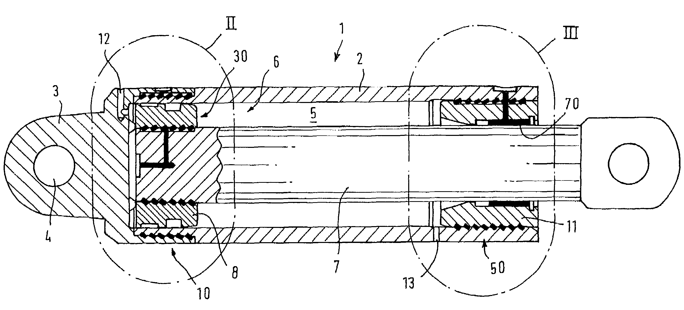
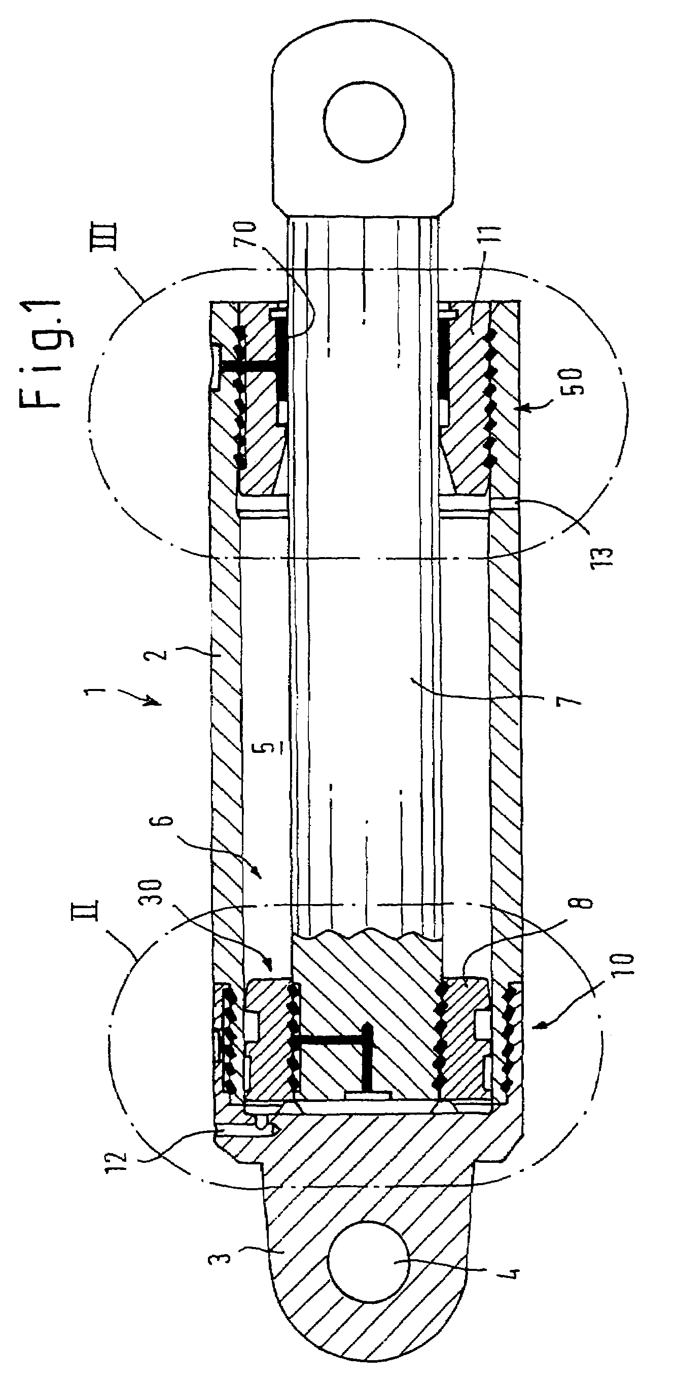
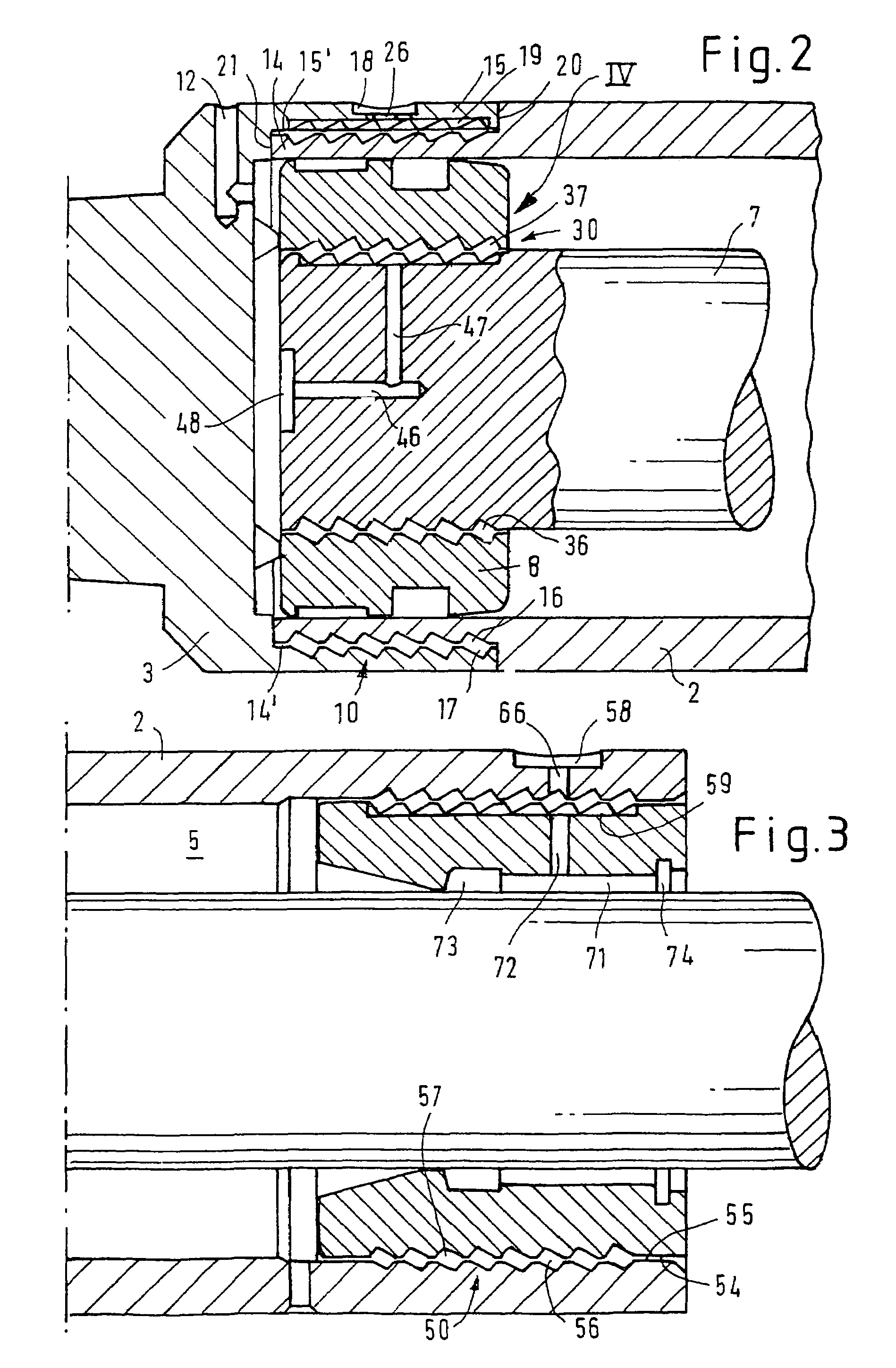
[0024]The hydraulic ram that is designated in total by 1 in FIG. 1 can e.g. be used as an advancing ram for shield advance, in order to advance a conveyor or an extraction machine in the direction of an excavation face and then by retracting the hydraulic ram, which can be activated in two directions, to move forward an shield support. The hydraulic ram 1 comprises an outer cylinder tube 2, which at the left-hand end in FIG. 1 is connected and at the same time sealed with a cylinder cover 3 by means of a first joining connection in accordance with the invention, denoted in total by 10, made of solidified plastic casting compound. On the cylinder cover 3 is integrally formed a linkage eye 4 for the jointed connection of the ram 1 to a support such as a bearing block. In the internal volume 5 of the hydraulic ram 1 a piston 6 is guided such that it can be moved; it consists of a piston rod 7 and an annular piston body 8, which are securely and in a sealed manner connected together by ...


PUM


Abstract

Joining connections are presented for joining the functional parts of hydraulic or pneumatic operating devices the joining connections including a first part exhibiting an external wall section and a second part exhibiting an internal wall section, which are joined together with mutually overlapping wall sections having depressions that form a cavity, in the connected state that is filled with a fluid casting compound of plastic that connects the two parts together by means of a positive form fit after hardening to prevent relative displacements between the two functional parts and to seal the separating gap clearance between the wall sections of the two functional parts.

Description

CROSS-REFERENCE TO RELATED APPLICATIONS[0001]This application is a national stage entry of international application number PCT / EP2003 / 009361, having international filing date Aug. 23, 2003, which was not published in English, which claims priority to German patent application number DE10241801, filed Sep. 6, 2002.BACKGROUND OF THE INVENTION[0002]The invention relates to a method for joining the functional parts of hydraulic or pneumatic working devices, in particular of operating rams such as props for underground mining, with a first part having an external wall section and a second part having an internal wall section, which parts are joined together with mutually overlapping wall sections are connected to each other in said overlapping sections. The invention also relates to a joining connection for the corresponding functional parts, which include a first part with an external wall section and a second part with an internal wall section, which parts can be joined together and c...

Claims


Application Information

Patent Timeline
Patent Type & Authority Patents(United States)
IPC IPC(8): E21D15/00E21D15/24E21D15/44F16B3/00F16B11/00
CPCE21D15/24E21D15/44F16B3/005Y10T403/475F16B11/008
Inventor ZINS, GUY
Owner CATERPILLER GLOBAL MINING EURO GMBH
Learn More