Mold closing unit

a technology of closing unit and mold, which is applied in the field of mold closing unit, can solve the problems of inability to ensure the lubrication of hinge pins, the inability to change mold inserts at the same time, and the inability to shorten the working stroke of electromechanical injection molding machines having toggle systems, etc., and achieve the highest quality, the effect of shortest possible dry run time and the highest possible productivity

Inactive Publication Date: 2006-02-28
NETABTAL MASCHEN
View PDF12 Cites 5 Cited by
  • Summary
  • Abstract
  • Description
  • Claims
  • Application Information

AI Technical Summary

Benefits of technology

[0012]This new solution permits some entirely new designs for both the short stroke or the working stroke and the long stroke or servicing stroke. A first embodiment is characterized in that it has an electric motor crank mechanism, preferably with a servo motor for the short stroke, by means of which a movable mold backing plate can be opened and closed quickly for the working stroke. The crank mechanism has an eccentric shaft and preferably two crank levers arranged in parallel, driven by a synchronous or asynchronous motor and acting symmetrically on the movable mold plate. The movable mold backing plate and the crank mechanism thus form a compact module anchored on the drive carrier plate, with the movable mold backing plate being guided on a guide. The enormous advantage achieved with a compact module consisting of the movable mold backing plate together with the crank mechanism is to be seen first of all in the production of an entire machine. The module permits economical modular assembly. If all the elements within one module are manufactured and fitted with the highest precision, this yields the highest precision for the overall functioning as well, despite the very short assembly time, because it can be based on the internal precision of the module. The crank mechanism can be utilized optimally in the crank function, as a pure impact function at the maximum required closing force by means of an eccentric shaft, and in the corresponding dead center range, the crank can be used for 100% unloading of the driving means or their bearings before this range. The greatest possible forces from the standpoint of mold closing can be reduced to purely static supporting forces which are more easily controlled per se. A not insignificant advantage is derived from the fact that not only any desired short working strokes can be used, but also the short stroke is kept at least approximately in the dead center position when the crank mechanism is in the closed position. For the open position, however, it can be stopped in any desired position outside the dead center position to shorten and optimize the dry run time. To ensure the greatest possible closing force or the largest possible closed position, the crank mechanism always moves at least approximately into a fixed preselected optimum position. Variations in mold thickness such as those due to temperature, for example, are adjusted by correcting the position of the mold backing plate on the nozzle end.
[0013]According to a second embodiment of this invention, the mold closing unit is characterized in that it has an electric motor column-type nut drive for the servicing stroke by means of which a mold backing plate on the nozzle end can be moved relative to the drive carrier plate for the servicing stroke. It is especially preferable here for the columns themselves to be drivable and for the mold backing plate on the nozzle end with the nuts mounted on it to be designed to be movable. Thus, the drive carrier plate becomes what is indicated by the phrase to the full sense of the term. The corresponding end plate becomes a carrier for the drives and is preferably fixedly connected to the machine stand. This brings several advantages at once. The static forces can be closed in the shortest distance. The highly dynamic forces are diverted or controlled from only one side, namely only from the drive carrier plate. In this way, possible vibrational processes can be kept under control more easily or compensated, while access for corrections can also be ensured at the same time.
[0014]The rotational drive for all columns takes place centrally, preferably by means of a toothed belt drive or a rim gear. It is also proposed that the central column-type nut drive should be designed as a final controlling element of the closing force regulation together with a force sensor arranged on a machine part as an actual value generator for detection of the closing force and a control device. Position detection of the stroke movement takes place advantageously by means of position detection in the servo motors themselves. These reproducible positions are used by the control / regulation and coordination of the various axles, e.g., also for control / regulation and synchronization of the actuation of the removing device and the mold closing axle. The control / regulation device is designed as a central adjustment for the servicing stroke and the working stroke with the required memories for storing formulations and programs. The control / regulation device is equipped for precise, coordinated control / regulation of the servo axles for the short stroke as well as the long stroke and with corresponding servo boosters for synchronous or asynchronous motors. It is important here that it has at least one independently controllable drive motor, preferably a servo motor for the working stroke and the servicing stroke. In the normal case, both drive sides are designed electromechanically for the working stroke and for the servicing stroke, with the direction of impact of the crank mechanism being arranged at least approximately symmetrically inside the column axles. The movable mold backing plate and the mold backing plate on the nozzle end are guided on a common guide. The column-type nut drive has at least three driven columns, preferably four, with the overdrive for the three or four columns being arranged on the outer end of the drive carrier plate and the overdrive for the crank mechanism being arranged on the inner end of the drive carrier plate.

Problems solved by technology

The result is unusually rapid changing of the mold inserts for injection molding machines.
However, today's electromechanical injection molding machines having a toggle system are not suitable for short working strokes, because then lubrication of the hinge pins is no longer guaranteed.

Method used


Image

  • Mold closing unit
  • Mold closing unit
  • Mold closing unit

Examples


Embodiment Construction

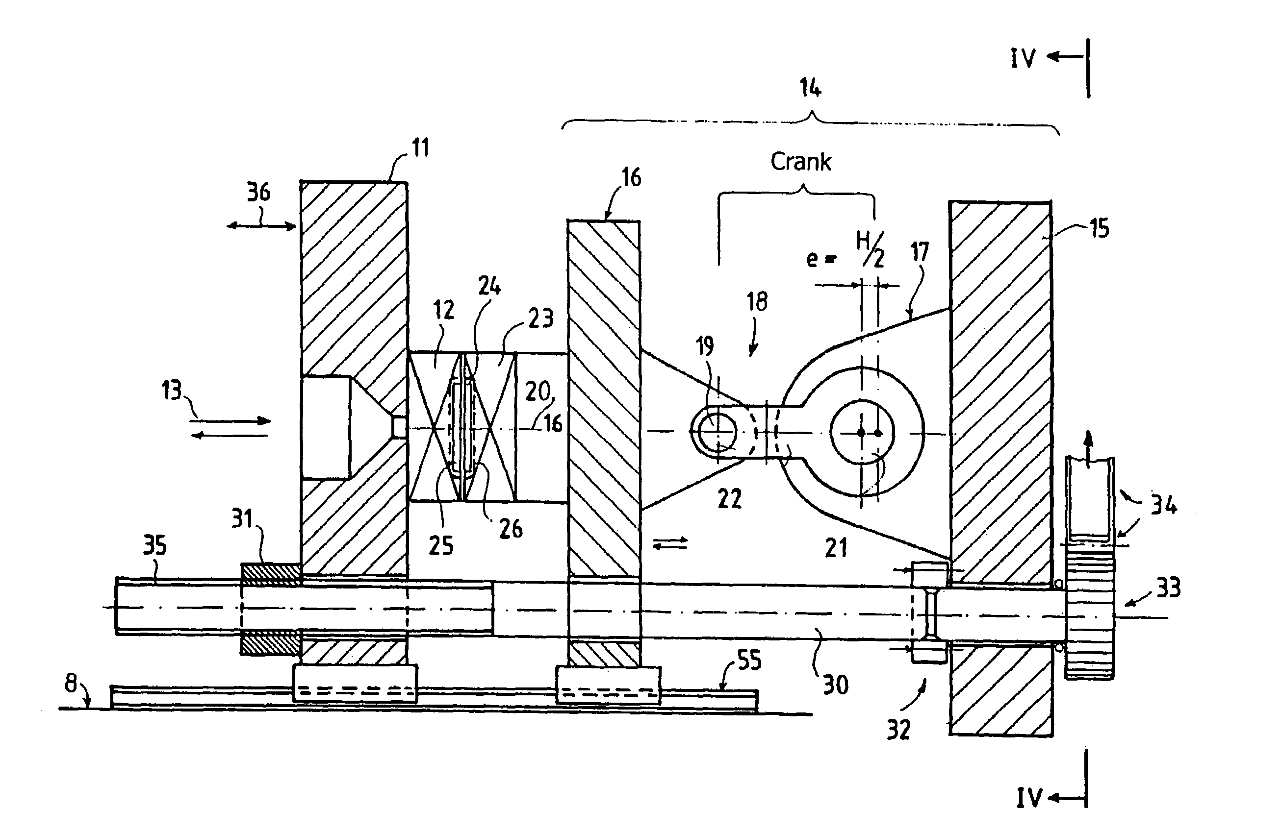
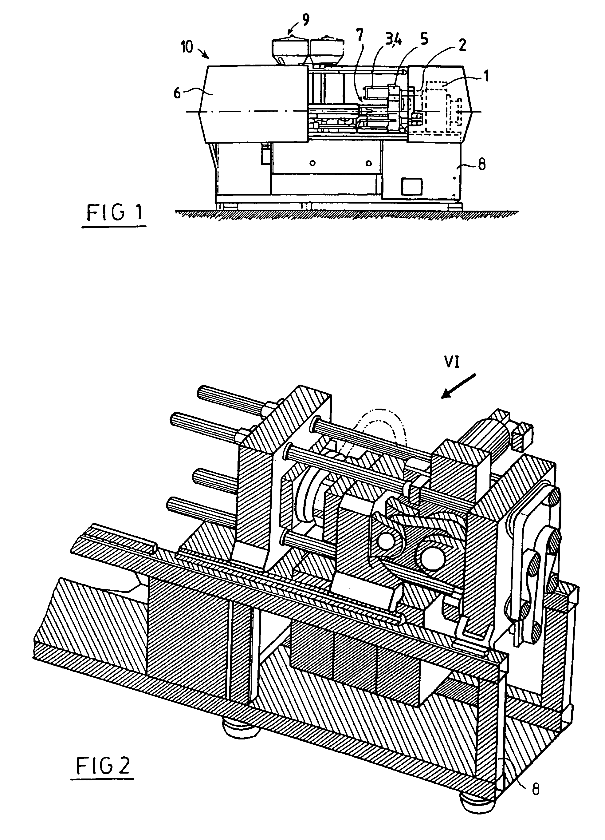
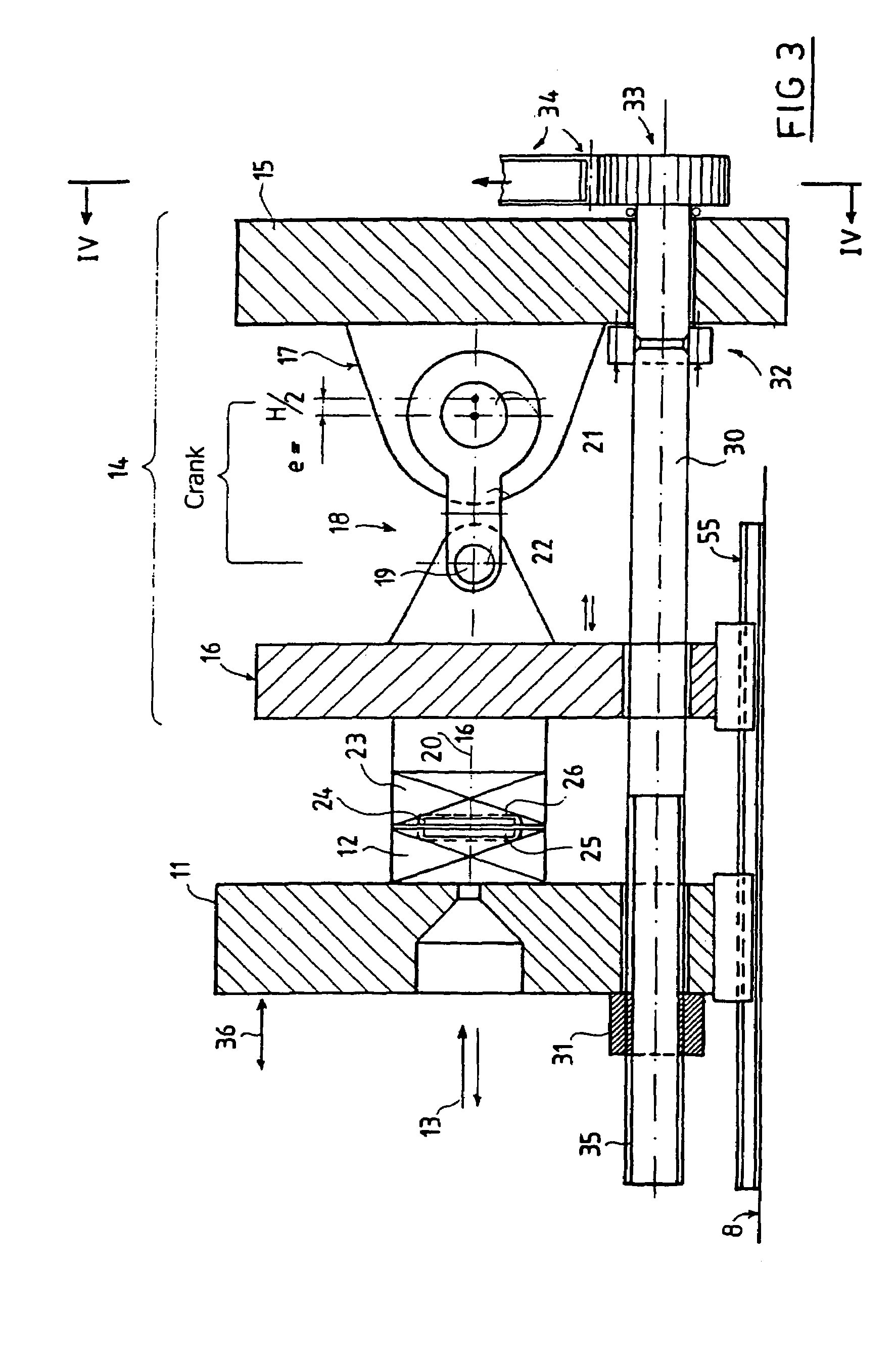
[0032]This novel solution makes it possible to design an entire machine for use in a clean room and to combine the advantages of machines equipped with a toggle system as well as those of machines equipped with fully hydraulic mold closing. An important advantage of the novel solution is that the dry run time can be designed to be extremely short, e.g., less than 0.3 second. In addition, even in the servicing stroke, movement with an accuracy in the micrometer range (thousandths of a millimeter) is guaranteed, so that the reproducibility of the closing movement operation, once it has been set, is fully guaranteed. The crank mechanism or eccentric drive also has the enormous advantage that the working stroke can be as small as desired, e.g., a crank radius of approx. 25–35 mm can be achieved easily.

[0033]With the solution according to FIG. 1, a CD can be produced in 3.7 seconds or less with the known state of the art. The known solution by the present applicant is a fully hydraulic m...


PUM

PropertyMeasurementUnit
stroke distanceaaaaaaaaaa
opening distanceaaaaaaaaaa
radiusaaaaaaaaaa

Abstract

The novel solution provides a closing part comprising an electromechanical drive for a CD injection molding machine having a working stroke and a servicing stroke. The entire mold closing unit is characterized by the combination of a short-stroke crank mechanism which is operated by an electric motor and which is provided for the working stroke and of a central electromotive column-type nut drive for the servicing stroke. According to the invention, synchronous motors or asynchronous motors are used with corresponding servo boosters to realize servo axles. The central column drive is used as a control element of the closing force control, together with a force sensor for detecting the closing force, as an actual value transmitter and as a control device.

Description

[0001]This is a continuation of application Ser. No. 09 / 913,047, filed on Nov. 14, 2001, now U.S. Pat. No. 6,796,783 which is a National Phase Application under 35 U.S.C. 371 of PCT International Application No. PCT / CH00 / 00069, filed on Feb. 9, 2000, which claims priority of Swiss Patent Application No. 249 / 99, filed on Feb. 10, 1999, the entirety of all of which are incorporated herein by reference.TECHNICAL FIELD[0002]This invention relates to a mold closing unit for an injection molding machine having a short working stroke and a longer servicing stroke, especially for production of disc-shaped parts.STATE OF THE ART[0003]In injection molding of flat parts such as compact discs, the opening stroke for the production cycle of the injection molding machine should be kept only as large as necessary for unmolding. Such compact discs are a few millimeters thick. Thus, theoretically, an opening slightly larger than 1 cm would be sufficient. Recent trends have in fact been toward short ...

Claims


Application Information

Patent Timeline
Patent Type & Authority Patents(United States)
IPC IPC(8): B29C45/64B29C45/17B29C45/66
CPCB29C45/17B29C45/66B29C2045/1791
Inventor WEINMANN, ROBERTSTILLHARD, BRUNOKEITEL, RALPH
Owner NETABTAL MASCHEN
Why Eureka
Try Eureka