
Cathodic protection of steel within a covering material

a technology of cathodic protection and covering material, which is applied in the field of cathodic protection of steel within a covering material, can solve the problems of significant cost disadvantage, limited commercial success of this method, and slow diffusion of corrosion products in solid phase, and achieve the effect of increasing the level of corrosion of the anod

Active Publication Date: 2007-06-05
WHITMORE DAVID W
View PDF10 Cites 21 Cited by
  • Summary
  • Abstract
  • Description
  • Claims
  • Application Information

AI Technical Summary

Benefits of technology

"The present invention provides an improved method of cathodic protection for steel within a covering material. The method involves using an anode material that provides ions to the steel through the covering material, while restraining the expansion of the anode material to prevent damage to the covering material. The method can be applied to repairs, overlays, or new structures, and can be used with various covering materials such as concrete, mortar, masonry, or stone. The method also includes the use of a reinforcing layer to enhance the connection between the anode material and the covering material. Overall, the method provides better protection against corrosion and damage to the steel while maintaining the appearance of the covering material."

Problems solved by technology

This commercial success of this method has been limited by the high cost of the jacket which can match the cost of the active components of the anode and coating and has little technical advantage, thus providing a significant cost disadvantage.
Diffusion of the corrosion products in solid phase is very slow.
Thus, even though the corrosion products may, over extended time periods, diffuse away from the anode body thus reducing forces from expansion, this diffusion in most cases is very slow and even where there are adjacent pores or openings in the covering material or in the anode structure itself, the corrosion products may generate significant expansion forces if the anode corrodes quickly, due to the slower diffusion movement of the corrosion products.
When so designed for rapid corrosion, the corrosion rate and the rate of corrosion product generation can exceed the ability of the system to absorb or carry away the corrosion products.
However this can be detrimental as it decreases structural strength and provides voids which can contain water with the: potential for freeze / thaw damage.

Method used


Image

  • Cathodic protection of steel within a covering material
  • Cathodic protection of steel within a covering material
  • Cathodic protection of steel within a covering material

Examples


Embodiment Construction

[0069]Attention is directed to the disclosure in the above PCT Applications by the present inventor which discloses the manufacture and use of anode bodies including anode materials, enhancement materials and methods of installation. The present embodiments disclosed herein include and use many of the constructions, arrangements and enhancement materials described therein.

[0070]The enhancement materials and the sacrificial anode material, such as zinc, can be pressed together to form a porous body as shown and described in the above applications, to which reference may be made for further details.

[0071]Preferably the anode body is formed simply by pressure on the particulate materials and typically pressures to effect sufficient compaction to maintain an integral structure will be in the range 5,000 psi-to 40,000 psi. Heat is therefore preferably not used but can be used to effect a melting of the particles at the points of engagement to enhance structural integrity. However heat ca...


PUM

PropertyMeasurementUnit
pressuresaaaaaaaaaa
sizeaaaaaaaaaa
lengthaaaaaaaaaa

Abstract

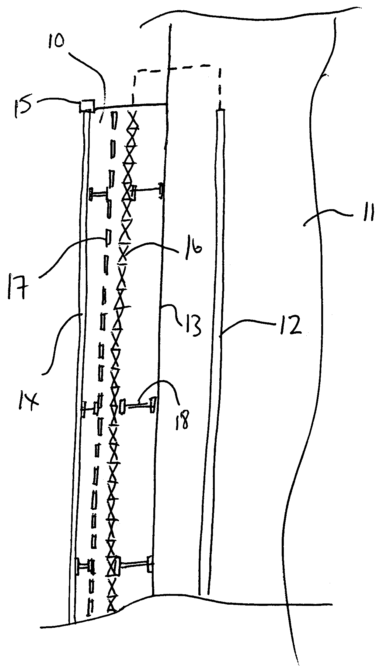
Cathodic protection of an existing concrete structure, including a steel member at least partly buried, such as steel rebar, in the concrete structure, is provided by embedding anodes into a fresh concrete layer applied over an excavated patch and / or as a covering overlay. The anodes are embedded at spaced positions or as an array in the layer and connected to the rebar. A reinforcing layer is applied to the anode or adjacent the anode to resist expansion of the anode body tending to cause cracking of the concrete caused by the larger volume of the corrosion products relative to the anode material. Pores are provided in the anode body so as to take up the corrosion products. The reinforcing layer can be provided in the actual anode body as a closed surface surrounding the anode material inside or may be provided in the concrete as a layer on top of the anode in an array form at or near the outer surface of the concrete.

Description

[0001]This invention relates to a method for cathodic protection of steel materials in a covering material such as mortar or concrete, which is particularly but not exclusively arranged for use with steel reinforced concrete structure.BACKGROUND OF THE INVENTION[0002]Cathodic protection of steel elements at least partly embedded in a surrounding layer is well known and methods for this purpose are described in PCT Application CA00 / 00101 filed 2 Feb. 2000 and published as WO 00 / 46422 and in PCT Application CA02 / 00156 filed 24 Jul. 2002 and published as WO 03 / 010358 both by the present inventor.[0003]In the first above application is disclosed an addition into the anode body of an enhancement material in the form of a humectant which enhances the ion flow and maintains the anode electrochemically active during its life. The enhancement material may be contained within the sacrificial anode material of the anode body rather than in a surrounding mortar or the like. In the second applic...

Claims


Application Information

Patent Timeline
Patent Type & Authority Patents(United States)
IPC IPC(8): C23F13/10C23F13/16
CPCC23F13/16C23F2201/02
Inventor WHITMORE, DAVID W.
Owner WHITMORE DAVID W
Learn More