
Method for producing a tubular spring and an actuator unit comprising one such tubular spring

a technology of tubular springs and actuator units, which is applied in the direction of machines/engines, soldering devices, applications, etc., can solve the problems of affecting the strength and service life of the actuator unit, affecting the quality of the tubular springs, and the known tubular springs are relatively expensive to manufacture, etc., to achieve the degree of precision of the tubular spring cutout, improve the dimensional stability of the required cylindrical outline, and improve the effect of surface quality

Inactive Publication Date: 2007-05-29
VITESCO TECH GERMANY GMBH
View PDF13 Cites 14 Cited by
  • Summary
  • Abstract
  • Description
  • Claims
  • Application Information

AI Technical Summary

Benefits of technology

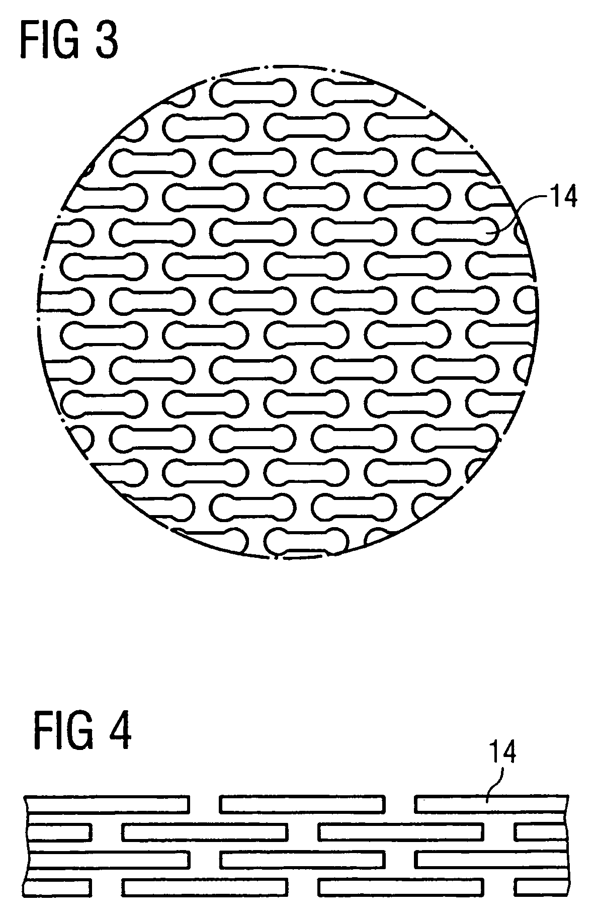
[0013]The oblong-shaped cutouts ensure that the hollow body exhibits sufficient strength even at the preloads generally applied to the piezoelectric actuator of approx. 800 to 1000 N and is at the same time sufficiently elastic to execute the longitudinal movements produced by the piezoelectric actuator. Using beam / jet cutting, it is possible to make very small, narrow cutouts in the cylindrical hollow body which could not be made in this shape using a punching process. This means that significantly more cutouts can be accommodated on the same area, resulting in a significant reduction in the spring rate of the jet-cut variant of the tubular spring. On the other hand, because of the required minimum dimensions of the punch and the associated punching time of the punching tool, typical dimensions of punched cutouts are specified within relatively tight limits. This means that with punched cutouts the number of cutouts per unit area is also limited, resulting in a relatively high spring rate.
[0016]Suitable beam / jet cutting methods include laser beam cutting, waterjet cutting or electron beam cutting. All these beam / jet cutting methods can be carried out with high precision and produce very exact and dimensionally stable workpieces.
[0017]A first embodiment of the method according to the invention provides that, by using a suitable filler inside the hollow cylinder during beam / jet cutting, a defined shaping of the beam / jet outlet edge is achieved and damage to the opposite side is prevented.
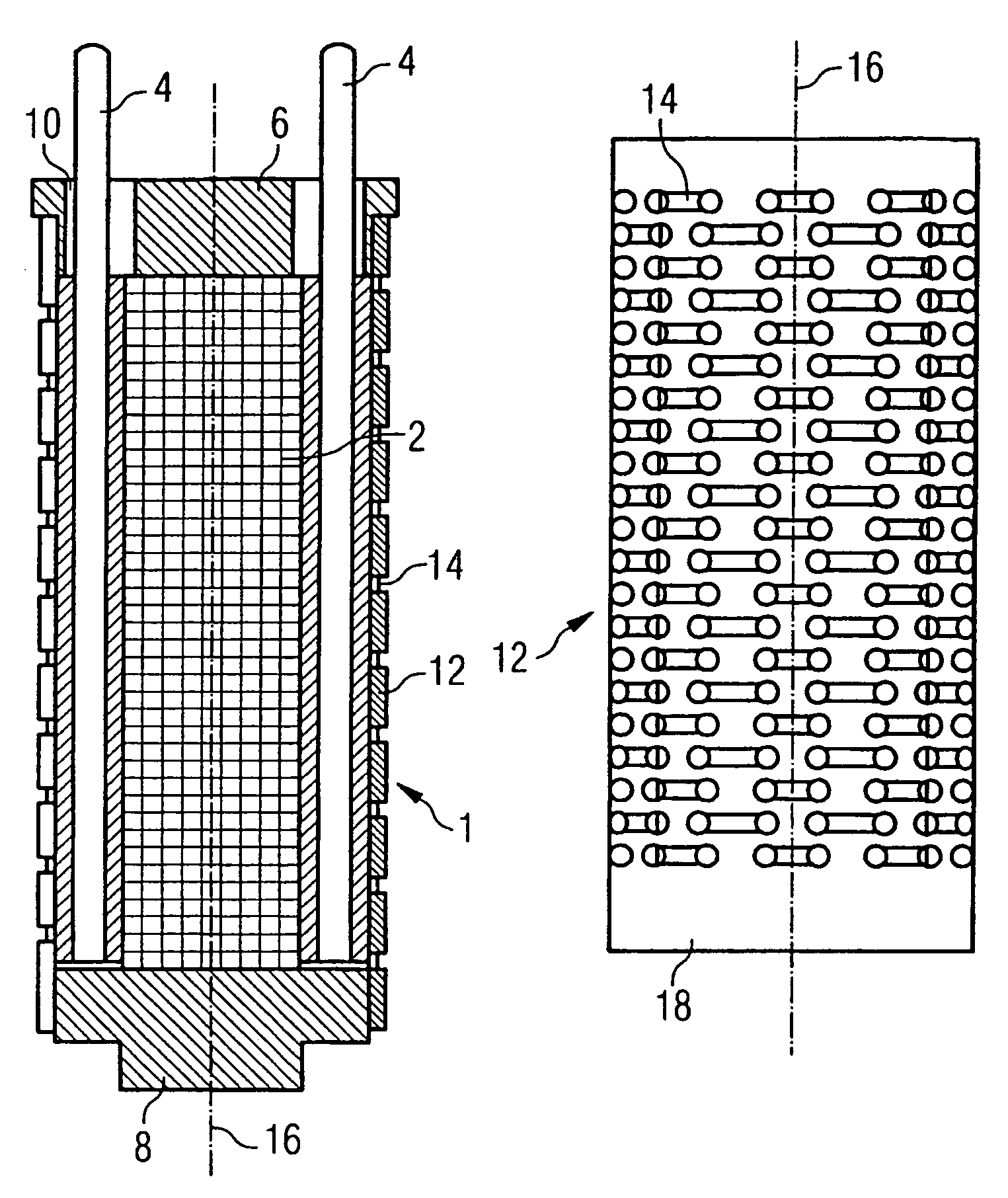
[0018]Another preferred variant of the method according to the invention provides that a longitudinal expansion direction of each cutout is in each case aligned essentially perpendicularly to the cylinder center line of the tubular spring. In this way a required spring constant can be imprinted on the tubular spring in the direction of its longitudinal axis. According to another embodiment of the invention, the cutouts are disposed in rows, the cutouts of adjacent rows each being laterally offset to one another. This arrangement has the advantage of providing ideal tubular spring compliance, as the alternately meeting spaces and cutouts can result in a possible pressing-in of the cutouts, with the intervening spaces being able to retain their shape in each case.
[0024]To summarize, the advantages of the method according to the invention are as follows: By using a beam / jet cutting method, a high degree of precision of the tubular spring cutouts can be achieved. Apart from the beam / jet cutting, no additional processing steps are required. Moreover, a high surface quality in the cutouts can be obtained that would not achievable by means of punching.
[0025]The use of seamless drawn steel tubes allows improved dimensional stability of the required cylindrical outline of the tubular spring. As there is no longitudinal weld, as is necessary in the case of known methods, fewer potential defects are produced in the metal. In addition, the usually necessary weld machining can be omitted.

Problems solved by technology

Moreover, mounting the actuator unit is time consuming and requires a high degree of maintenance, as the preload exerted on the piezoelectric actuator by the tubular spring must be re-adjusted each time the unit is fitted and removed.
With the tubular springs used, there is the additional problem that, in order to achieve sufficient elasticity of longitudinal movement of the piezoelectric actuator, the tubular spring must be extremely thin-walled, which adversely affects the strength and service life of the actuator unit.
This known tubular spring is relatively expensive to manufacture, as the cutouts are produced in a punching process.

Method used


Image

  • Method for producing a tubular spring and an actuator unit comprising one such tubular spring
  • Method for producing a tubular spring and an actuator unit comprising one such tubular spring
  • Method for producing a tubular spring and an actuator unit comprising one such tubular spring

Examples


Embodiment Construction

[0032]FIG. 1 shows an actuator unit 1 consisting of a plurality of stacked individual piezoelectric elements. Electrical voltage is applied to the piezoelectric actuator unit 1 by means of contact pins 4. The contact pins 4 are each disposed along the actuator unit 1 and are in electrical contact with the actuator element 2. By applying a voltage between the contact pins 4, a longitudinal expansion of the piezoelectric actuator element 2 is produced which can be used e.g. for actuating an injection valve of an internal combustion engine. The piezoelectric actuator element 2 with the contact pins 4 is disposed in a cylindrical hollow body implemented as a tubular spring 12.

[0033]The end faces of the piezoelectric actuator element 2 bear on a cover plate 6 or base plate 8 as applicable, the upper cover plate 6 having bushings 10 through which the contact pins 4 extend. The cover plate 6 and the base plate 8 are each connected to the tubular spring 12 with a form and / or force fit, pref...


PUM

PropertyMeasurementUnit
thicknessaaaaaaaaaa
thicknessaaaaaaaaaa
forceaaaaaaaaaa

Abstract

A method for producing a tubular spring (12) in the form of a cylindrical hollow body, especially for pre-tensioning a piezoelectric actuator element (2) of an actuator unit (1) of a fuel injector comprises the step of providing a thin-walled, solid-drawn steel tube with a plurality of regularly arranged longish recesses (14) by means of laser cutting. Thus, an actuator unit (1) comprises a piezoelectric actuator element (2) which is arranged in a thin-walled cylindrical hollow body, wherein the hollow body being elastically embodied and pre-tensioning the actuator element (2). Furthermore, the hollow body is a solid-drawn steel tube which is provided with a plurality of longish recesses (14).

Description

CROSS REFERENCE TO RELATED APPLICATION[0001]This application is a continuation of copending International Application No. PCT / DE02 / 03718 filed Oct. 1, 2002 which designates the United States, and claims priority to German application no. 101 49 746.6 filed Oct. 9, 2001.TECHNICAL FIELD OF THE INVENTION[0002]The invention relates to a method for producing a tubular spring, more specifically for an actuator unit of a fuel injector, and an actuator of this kind comprising a tubular spring.DESCRIPTION OF THE RELATED ART[0003]The new generation of fuel injection systems have piezoactuator elements as switching and actuating devices. These so-called piezo stacks comprising piezo units disposed one on top of the other are elastically preloaded for durability reasons. The preloading elements used for this purpose must apply very high preloading forces and be of compact size. Moreover, they must exhibit a relatively low spring constant and be of simple and rugged design. Durability with respe...

Claims


Application Information

Patent Timeline
Patent Type & Authority Patents(United States)
IPC IPC(8): B23P15/16B21D51/16F02M63/00F16F1/02H02N2/04H10N30/88
CPCF16F1/028H01L41/053F02M2200/21F16F2226/00Y10T29/496Y10T29/49405Y10T29/49609H10N30/886
Inventor JOVOVIC, DEJANLEWENTZ, GUNTERVOIGT, ANDREASZUMSTRULL, CLAUS
Owner VITESCO TECH GERMANY GMBH
Learn More