
Magnetoresistive effect element, a magnetic head, and a magnetic reproducing apparatus therewith

a magnetoresistive element and effect element technology, applied in the field of high sensitivity magnetoresistive elements, can solve the problems of insufficient surface recording density of the tmr head, inability to realize a magnetoresistive element that fully utilizes the real strength of the tmr element, and difficulty in accurate operation of the magnetic head, so as to achieve high recording density, improve the sensitivity of the magnetoresistive effect element, and improve the effect of sensitivity

Inactive Publication Date: 2007-05-22
FUJITSU LTD
View PDF33 Cites 1 Cited by
  • Summary
  • Abstract
  • Description
  • Claims
  • Application Information

AI Technical Summary

Benefits of technology

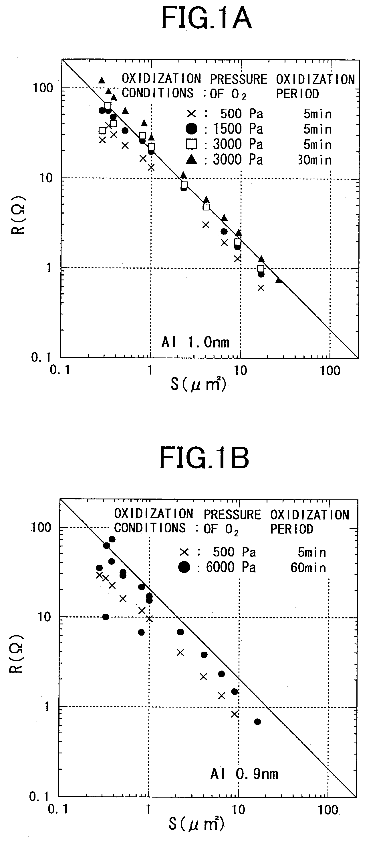
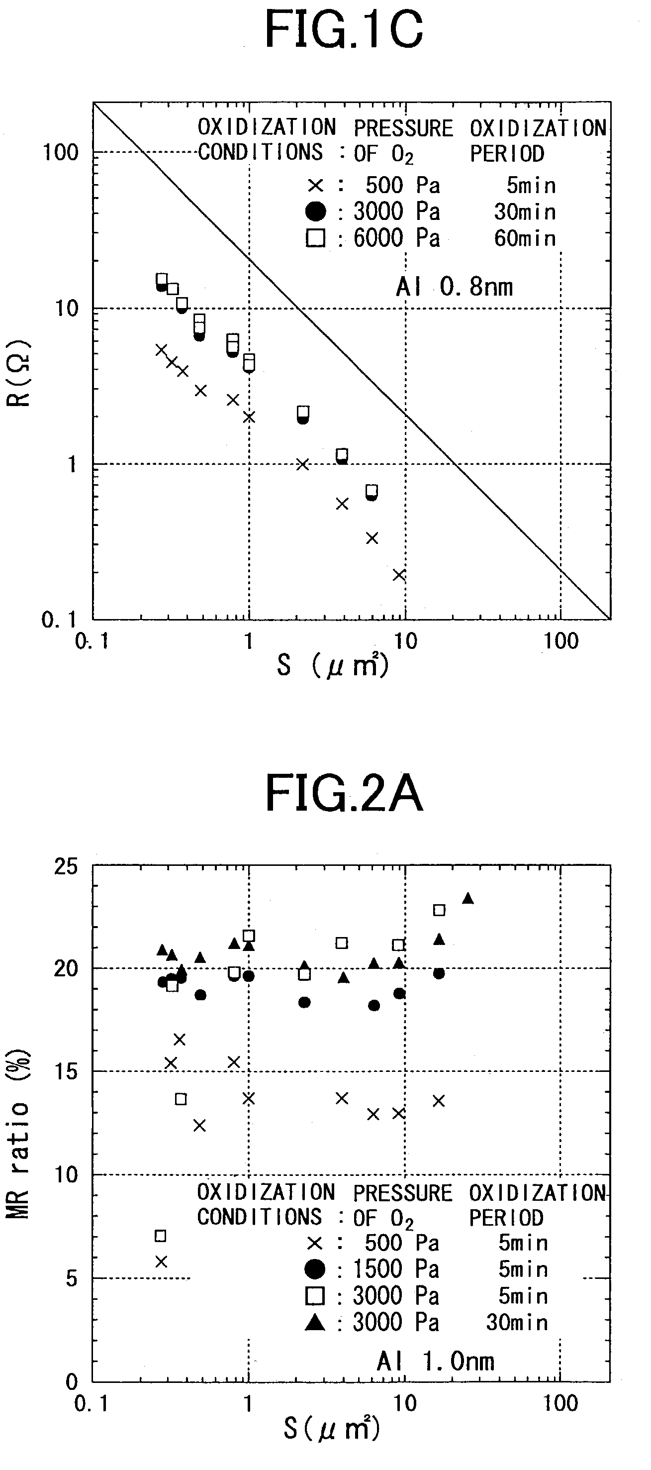
[0009]From FIG. 1A through FIG. 1C, it is deduced that the junction resistance R of a TMR element becomes lower as the tunnel insulation layer is made thin, and as the oxidization processing is weakened by lowering the pressure of O2(Pa) and by shortening the oxidization period. For example, in the case of FIG. 1C, where the TMR element was produced by 0.8 nm thick aluminum under 3000 Pa and natural oxidization for 30 minutes, the surface resistance is lowered to approximately 4 Ω / μm2.
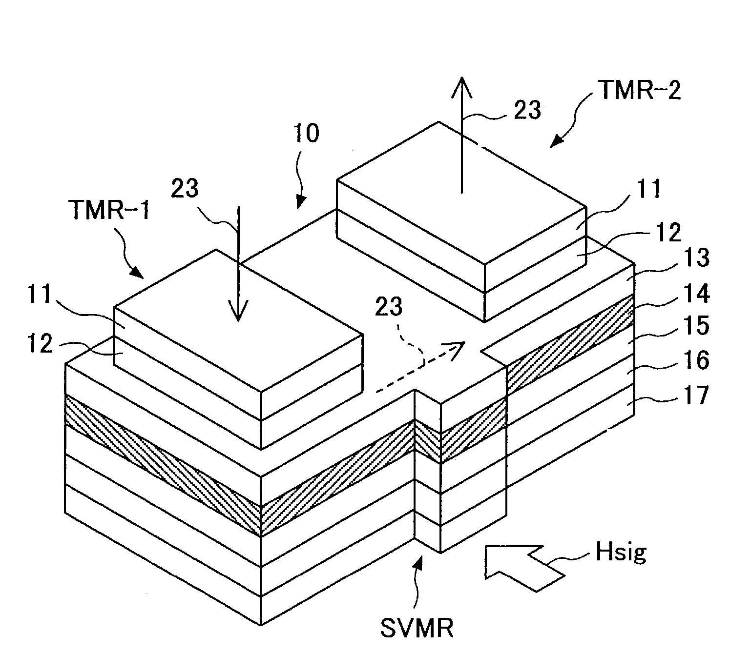
[0018]In this manner, the problem of the conventional TMR element is compensated for by the SVMR element part, and a higher density magnetoresistive effect element can be provided. That is, with the TMR-SVMR element of the present invention, the tunnel insulation layer of the TMR element can be made thin, and a voltage applied for detecting external magnetic data is shared by the TMR element part and the SVMR element part, thus the voltage dependency of the TMR is alleviated.
[0019]Further, it is desirable that a flux guide be provided to the free magnetic layer of the TMR-SVMR element. Since the SVMR element part is formed in one body, even if the flux guide structure is provided to the free magnetic layer, the degradation of the reproduction output, the problem with the conventional TMR element, can be compensated for, and a magnetoresistive effect element with high sensitivity can be attained.
[0024]Since this TMR-SVMR-TMR element detects external magnetic data with the three magnetoresistive effect elements, high sensitivity is available. The tunnel insulation layer of the TMR element of the TMR-SVMR-TMR element can be made thin. Sense current applied in order to detect the external magnetic data flows perpendicularly through the lamination surface of the first TMR element part, flows in the direction of the surface (horizontal) in the SVMR element part, and flows perpendicularly through the second TMR element part to the lamination surface. Therefore, the voltage applied is approximately equally shared by the three element parts, and the voltage dependency of the TMR is alleviated.
[0026]As for the TMR-SVMR element that can be realized in a plurality of formations, as described above, the SVMR element can be made a specular type (i.e., mirror reflective structure) by forming an oxidized layer in the direction of the surface (i.e., horizontally), such that electrons of the free magnetic layer are reflected, thereby the sensitivity of the magnetoresistive effect element is further improved.

Problems solved by technology

Although there are trial production reports concerning TMR heads from a plurality of companies, the surface recording density of the TMR head has not yet reached a satisfactory level according to these reports.
The TMR elements that have been made so far have junction resistance values ranging between approximately 20 and 40 Ω / μm2, and MR ratios ranging between approximately 7 and 20%, which are not satisfactory to realize a magnetoresistive element that fully utilizes the real strength of a TMR element.
Because of this, problems arise, such as degradation of S / N, an increase in delay, etc., and accurate operations of the magnetic head become difficult.

Method used


Image

  • Magnetoresistive effect element, a magnetic head, and a magnetic reproducing apparatus therewith
  • Magnetoresistive effect element, a magnetic head, and a magnetic reproducing apparatus therewith
  • Magnetoresistive effect element, a magnetic head, and a magnetic reproducing apparatus therewith

Examples


first embodiment

[0037]FIG. 3A through FIG. 3D show the present invention. FIG. 3A through FIG. 3D show a magnetic head 100 that includes a triple composite type magnetoresistance effect element or magnetoresistive effect element that includes a TMR element, a SVMR element and another TMR element connected in series. FIG. 3A is a plan drawing of the magnetic head 100 viewed from the top. FIG. 3B is a sectional drawing showing the section A—A of FIG. 3A. FIG. 3C is a sectional drawing showing the section B—B of FIG. 3A. FIG. 3D is a sectional drawing showing the section C—C of FIG. 3A.

[0038]An outline composition of the magnetic head 100 is explained with reference to FIG. 3A through FIG. 3C. The magnetic head 100 includes a seed layer 21, on the upper surface of which a triple composite type magnetoresistive effect element 10 is arranged, on opposing sides of which, two hard magnetic films 19 and 19 are arranged, which are for forming the magnetization direction of a free magnetic layer 14 into a si...

second embodiment

[0057]As a variation of the second embodiment, a structure wherein only the free magnetic layer 14 has a flux guide is also employable.

[0058]FIG. 8 shows the TMR-SVMR according to the third embodiment of the present invention. In this embodiment, the free magnetic layer 14, serving as the common layer, is also sandwiched by the TMR section provided in the upper part and the SVMR section provided in the lower part. In the third embodiment, the same reference marks are given to the components that are the same as the first embodiment.

third embodiment

[0059]Although the magnetoresistive element according to the present invention is structured by simply compounding the TMR element and the SVMR element, a magnetoresistive element with high sensitivity is available, because the SVMR element is added to a conventional magnetoresistive element that is constituted only from a TMR element. The sense current 23 flows perpendicular to the lamination through the TMR element part and the SVMR element part.

[0060]Here, an example of the magnetic recording and reproducing apparatus 70 in which is installed the magnetic head 100 of the present invention is briefly explained. FIG. 9 shows the principal parts of the magnetic recording and reproducing apparatus 70. A hard disk 71 as a magnetic recording medium is installed in the magnetic recording and reproducing apparatus 70, and a rotational drive is carried out.

[0061]The SVMR element 10 scans the surface of the hard disk 71 at a predetermined floating height from the surface such that a magnet...


PUM

PropertyMeasurementUnit
thicknessaaaaaaaaaa
thicknessaaaaaaaaaa
thicknessaaaaaaaaaa

Abstract

A magnetoresistive effect element is a compound lamination including a first anti-ferromagnetic layer, a first fixed magnetic layer, a tunnel insulation layer, a free magnetic layer, a non-magnetic metal layer, a second fixed magnetic layer, and a second anti-ferromagnetic layer such that a TMR element and a SVMR element are formed, sharing the free magnetic layer.

Description

[0001]This is a continuation of International PCT Application No. PCT / JP00 / 09107 filed Dec. 21, 2000.TECHNICAL FIELD[0002]The present invention generally relates to a high sensitivity magnetoresistive element, and especially relates to a magnetoresistive effect element that combines a tunnel type magnetoresistive effect element (TMR element) and a spin valve type magnetoresistive effect element (SVMR element).BACKGROUND ART[0003]In recent years, recording density of magnetic memory media has been remarkably increasing. For example, the surface recording density of a hard disk drive unit has been doubling each year, and it is considered that the spin valve type magnetoresistive effect head currently in use will reach the limit of its reproduction capability in the near future. Therefore, it is necessary to develop a magnetic effect element with higher sensitivity, which can form a magnetic head.[0004]In a situation like this, the tunnel type magnetoresistive effect type head (TMR hea...

Claims


Application Information

Patent Timeline
Patent Type & Authority Patents(United States)
IPC IPC(8): G11B5/127G01R33/09G11B5/012G11B5/31G11B5/39H01F10/32H01L43/08
CPCB82Y10/00B82Y25/00G01R33/093G11B5/3909H01F10/3254H01F10/3268H01L43/08G11B5/3903G11B5/012G11B5/3143H01F10/3295G11B2005/3996H10N50/10G11B5/39
Inventor ZHANG, YIQUNKIKUCHI, HIDEYUKISATO, MASASHIGEKOBAYASHI, KAZUOKANAI, HITOSHI
Owner FUJITSU LTD
Learn More