Method and apparatus for spiral scan computed tomography

a computed tomography and spiral scan technology, applied in tomography, instruments, applications, etc., can solve the problems of inability to adapt the image plane adequately well to the spiral path, inability to optimize the detector area available, and inability to apply the radiation dose to the patient for image acquisition (detector and thus dose utilization)

Inactive Publication Date: 2007-05-08
SIEMENS HEALTHCARE GMBH
View PDF7 Cites 13 Cited by
  • Summary
  • Abstract
  • Description
  • Claims
  • Application Information

AI Technical Summary

Benefits of technology

[0017]As a result, it is possible to achieve at least approximately complete detector and dose utilization even given values of the pitch falling below the maximum pitch.

Problems solved by technology

Fundamentally, the method disclosed in U.S. Pat. No. 5,802,134 can be employed for arbitrary values of the pitch p. However, an optimum utilization of the detector area available and thus of the radiation dose applied to the patient for image acquisition (detector and thus dose utilization), is not possible below the maximum pitch Pmax.
This is because even though a given transverse slice, i.e. a slice of the subject residing at a right angle relative to the system axis z, is scanned over a spiral segment that is longer than 180° plus the fan or cone angle, only a spiral segment having the length 180° plus the cone angle can be utilized for values of the pitch p below the maximum pitch Pmax, since the utilization of a longer spiral segment would make it impossible to adapt the image plane adequately well to the spiral path.

Method used


Image

  • Method and apparatus for spiral scan computed tomography
  • Method and apparatus for spiral scan computed tomography
  • Method and apparatus for spiral scan computed tomography

Examples


Embodiment Construction

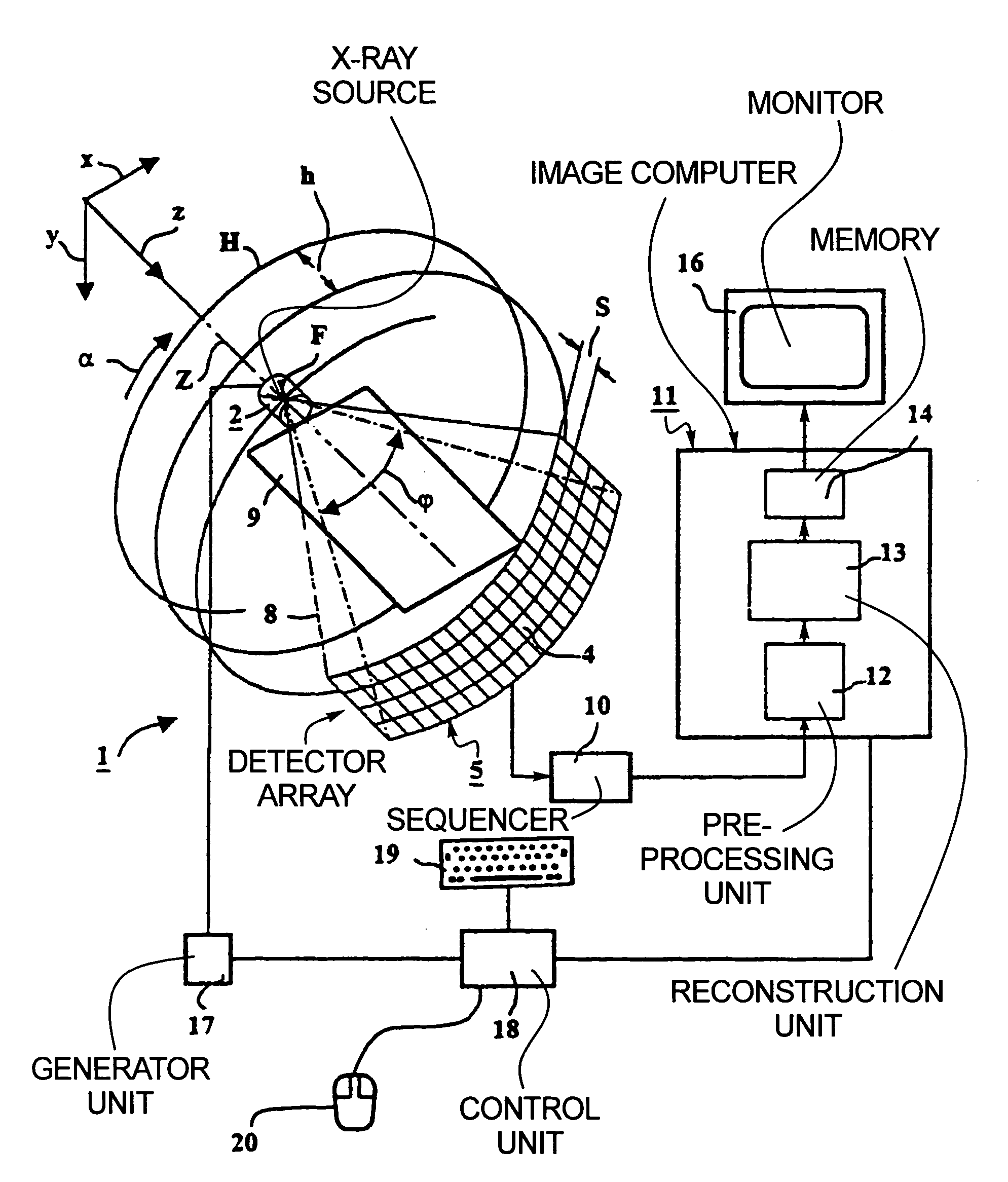
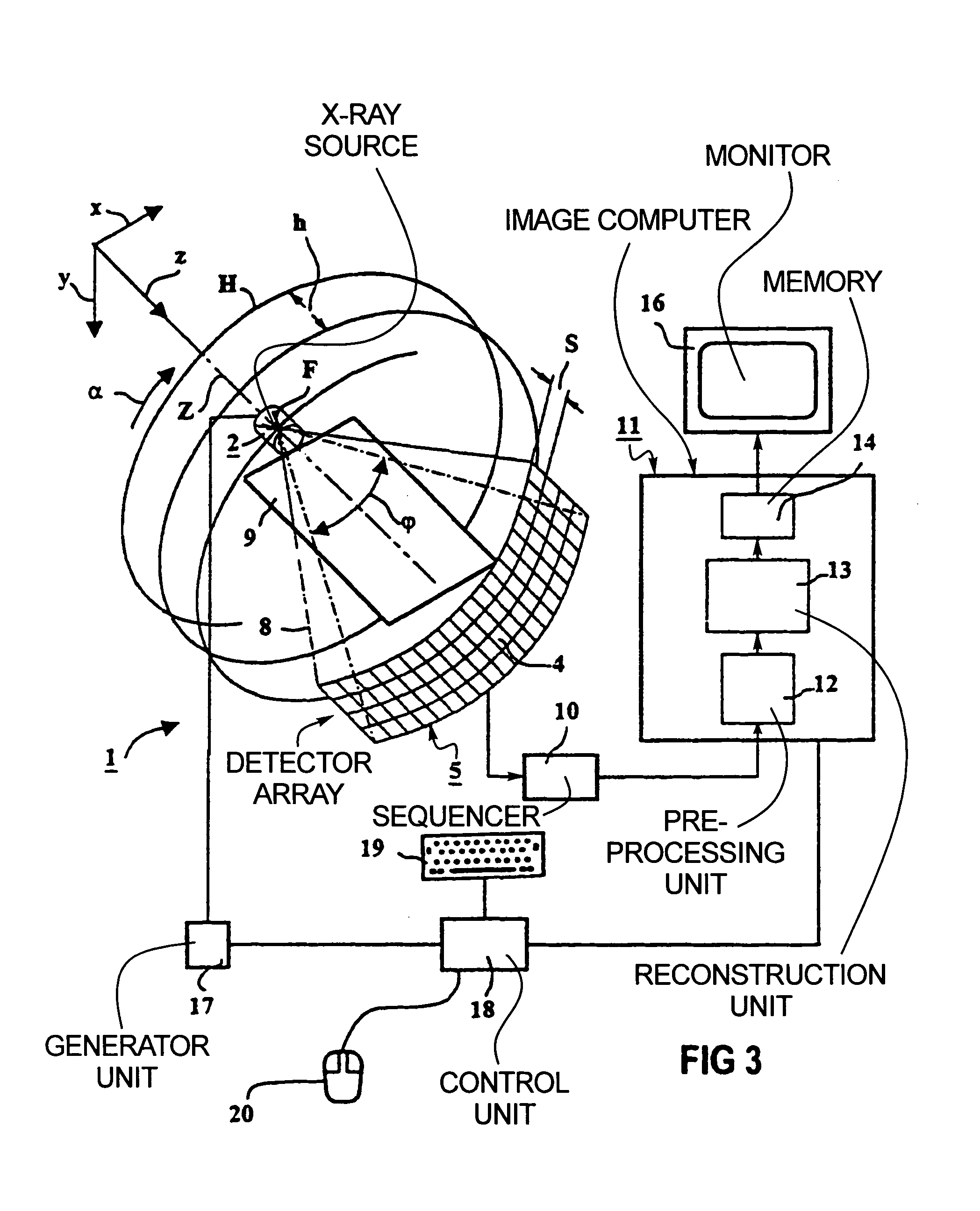
[0051]FIGS. 3 and 4 show an inventive multi-slice CT apparatus of the third generation suitable for the implementation of the inventive method. The measurement arrangement 1 thereof has an x-ray source 2 with a source-proximate radiation diaphragm 3 (FIG. 4) and a detector array 5 fashioned as a planar array having a number of rows and columns of detector elements—one of these is referenced 4 in FIG. 3—and having a detector-proximate radiation diaphragm 6 (FIG. 4). The x-ray source 2 with the radiation diaphragm 3 and the detector array 5 with the radiation diaphragm 6 are mounted to a live frame 7 also referred to below as gantry, as shown in FIG. 4. These components are disposed opposite one another such that a pyramidal x-ray beam that emanates from the x-ray source 2 during operation of the CT apparatus, and is gated by the adjustable radiation diaphragm 3 (whose edge rays are referenced 8) is incident onto the detector array 5. The radiation diaphragm 6 is set, with respect to ...


PUM


Abstract

In a method for computed tomography and a computed tomography apparatus for scanning a subject with a conical ray beam emanating from a focus that detects a matrix-like detector array, the focus is moved relative to the subject on a spiral path around a system axis, and the detector array supplies output data corresponding to the incident radiation, and images having an inclined image plane are reconstructed from output data respectively supplied during the movement of the focus on a spiral segment, the image planes of these images are inclined by an inclination angle γ around a first axis intersecting the system axis at a right angle and also are inclined by a tilt angle δ with respect to the system axis around a second axis that intersects the first axis as well as the system axis at a right angle.

Description

BACKGROUND OF THE INVENTION[0001]1. Field of the Invention[0002]The present invention is directed to a method for operating a computed tomography apparatus, and to a computed tomography apparatus, of the type for conducting a spiral scan of an examination subject.[0003]2. Description of the Prior Art[0004]Methods for operating a computed tomography apparatus are known wherein, for scanning a subject with a conical ray beam emanating from a focus which strikes with a matrix-like detector array for detecting the radiation, the focus is moved relative to the subject on a spiral path around a system axis. The detector array supplies output data corresponding to the incident radiation, and images relative to the system axis are reconstructed from the output data respectively supplied during the movement of the focus has each spiral segment. Computed tomography (CT) systems are known having a radiation source with a focus from which a conical ray beam emanates, a matrix-like detector arra...

Claims


Application Information

Patent Timeline
Patent Type & Authority Patents(United States)
IPC IPC(8): G06K9/00A61B6/03
CPCA61B6/032A61B6/4085A61B6/027Y10S378/901
Inventor BRUDER, HERBERTFLOHR, THOMASKACHELRIESS, MARCSCHALLER, STEFANSTIERSTORFER, KARL
Owner SIEMENS HEALTHCARE GMBH
Why Eureka
Try Eureka