
Frequency stabilization of chopper-stabilized amplifiers

a technology of amplifiers and stabilizers, applied in the direction of pulse techniques, amplifiers with semiconductor devices/discharge tubes, electronic switching, etc., can solve problems such as near-unstable behavior

Inactive Publication Date: 2007-04-24
MAXIM INTEGRATED PROD INC
View PDF12 Cites 26 Cited by
  • Summary
  • Abstract
  • Description
  • Claims
  • Application Information

AI Technical Summary

Problems solved by technology

If the amplifier is used in high-gain feedback settings, the 12 dB / oct part may cause undesired near-unstable behavior.

Method used


Image

  • Frequency stabilization of chopper-stabilized amplifiers
  • Frequency stabilization of chopper-stabilized amplifiers
  • Frequency stabilization of chopper-stabilized amplifiers

Examples


Embodiment Construction

Description of Embodiments as Applied to OpAmps

[0026]To straighten out the bubble in the frequency response described before, chopper-stabilized methods may be combined with the prior art multipath hybrid nested Miller compensation in two steps.

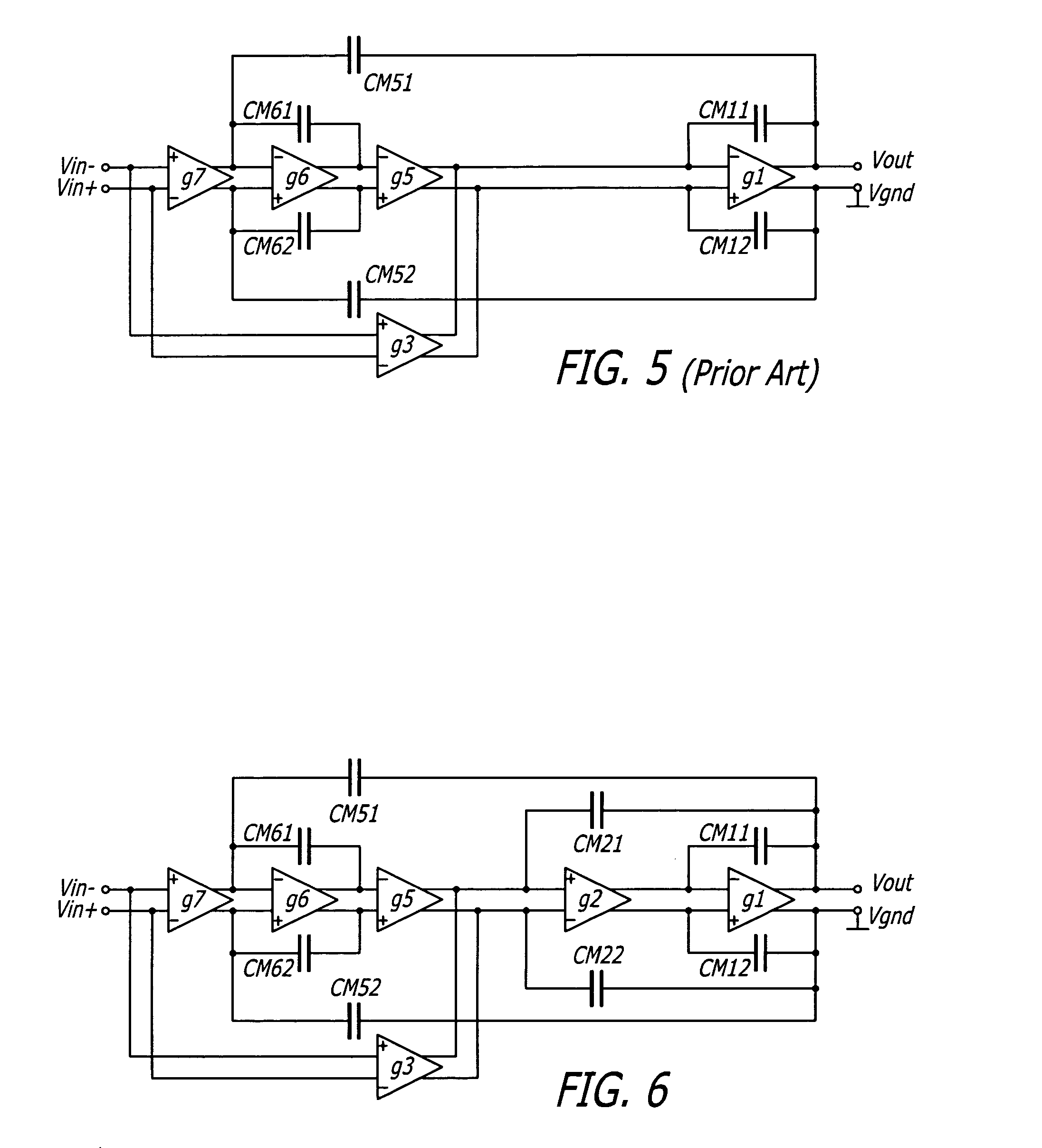
[0027]The circuit of FIG. 5 may be extended with another amplifier G2 in the gain path. To make it stable, a double nested structure is added at the output by CM21 and CM22. The result is the multipath hybrid double-nested Miller compensation structure of FIG. 6. It has the desired straight 6 dB / oct roll off of the frequency characteristic.

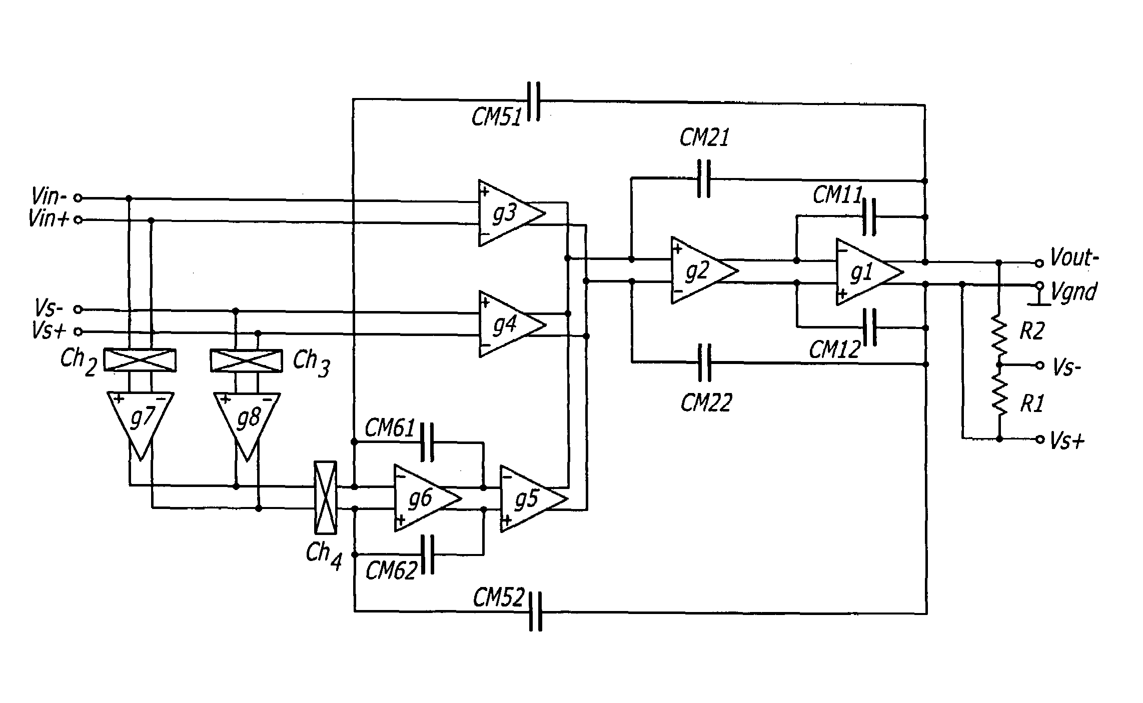
[0028]Now chopper-stabilization can be added in the amplifier of FIG. 6. This results in the chopper stabilized OpAmp with multipath hybrid double-nested Miller compensation of FIG. 7. The feed forward nested capacitors CM61 and CM62 can now be chosen to fit the requirements of an integrator of the signal from amplifier G7 in the chopper-stabilized amplifier. At a right choice of all amplifier and capacitor...


PUM


Abstract

Frequency stabilization of chopper-stabilized amplifiers using multipath hybrid double-nested Miller compensation. The compensation may provide a desired 6 dB / oct roll off for both instrumentation amplifiers and operational amplifiers. Various embodiments are disclosed.

Description

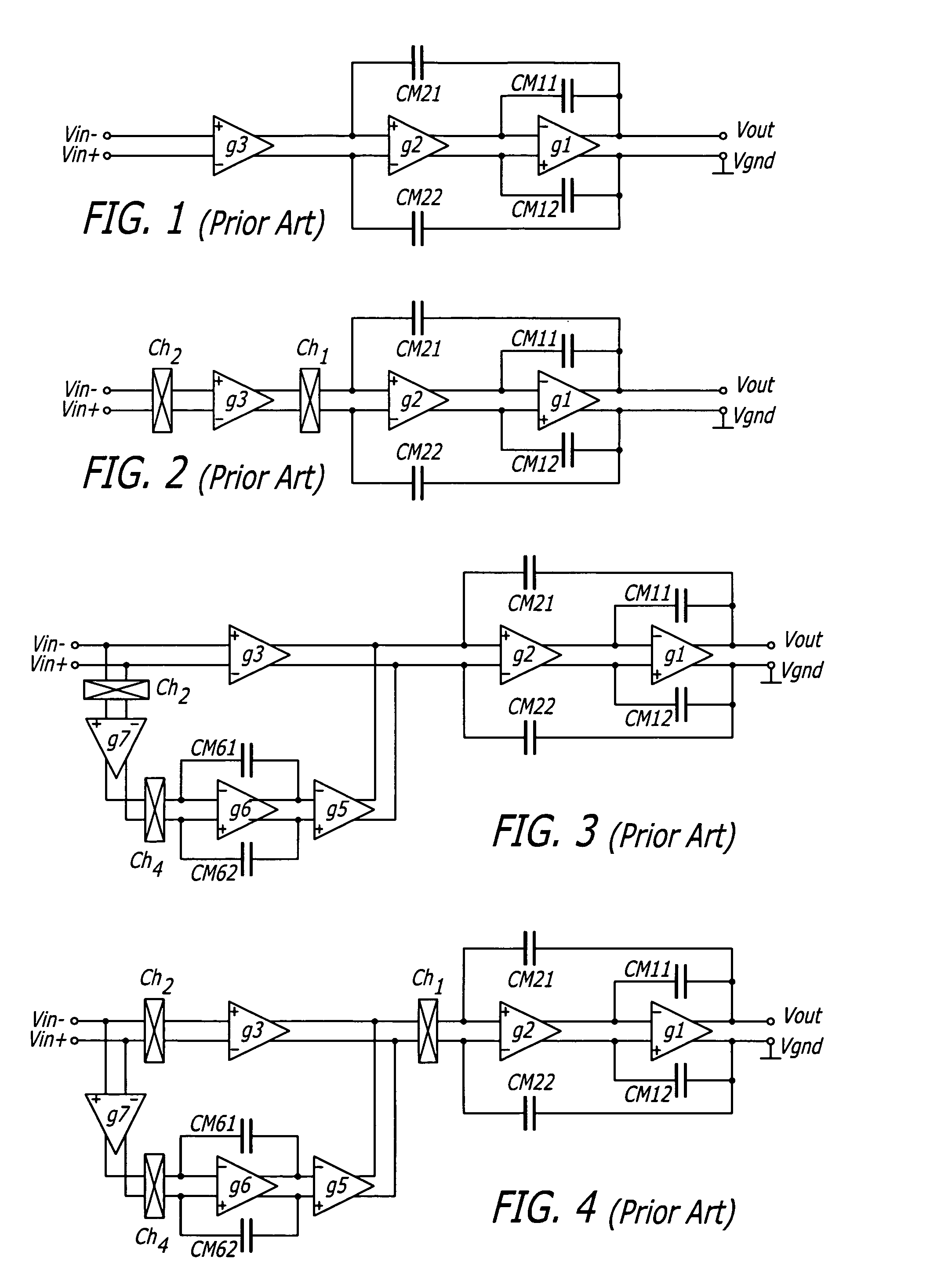
BACKGROUND OF THE INVENTION[0001]1. Field of the Invention[0002]The present invention relates to the field of chopper stabilized amplifiers.[0003]2. Prior Art[0004]Frequency compensation for precision OpAmps (operational amplifiers) has a large history. FIG. 1 illustrates the nested Miller compensation scheme of U.S. Pat. No. 4,559,502 for compensation of a 3-stage amplifier (multipath hybrid nested Miller compensation is shown in U.S. Pat. No. 5,486,790). The single output stage does not need frequency compensation. The compensation capacitors CM11 and CM12 compensate for the extra gain of amplifier G2, while CM21 and CM22 compensate for the extra gain of amplifier G3.[0005]For obtaining a low offset, choppers can be placed around the input amplifier G3. This is shown in FIG. 2. The offset of amplifier G3 will appear as a residual square wave at the output as fed back to the input of the amplifier. The average offset is nearly zero.[0006]The chopper stage amplifier G3 requires comp...

Claims


Application Information

Patent Timeline
Patent Type & Authority Patents(United States)
IPC IPC(8): H03F1/02
CPCH03F1/08H03F3/387H03F3/45475H03F3/45986H03F2200/153H03F2200/261H03F2203/45264
Inventor HUIJSING, JOHAN HENDRIKFONDERIE, MAARTEN JEROENSHAHI, BEHZAD
Owner MAXIM INTEGRATED PROD INC
Learn More