
Methods and apparatus for electric power grid frequency stabilization

a technology of electric power grid and frequency stabilization, which is applied in the direction of electric generator control, machines/engines, transportation and packaging, etc., can solve the problems of increasing or decreasing the consumption of power generation systems, reducing the frequency of grid, and increasing the frequency of grid

Active Publication Date: 2007-09-25
GE INFRASTRUCTURE TECH INT LLC
View PDF18 Cites 31 Cited by
  • Summary
  • Abstract
  • Description
  • Claims
  • Application Information

AI Technical Summary

Benefits of technology

The solution enables a controlled and efficient response to both under-frequency and over-frequency conditions, reducing stress on components, improving thermal efficiency, and maintaining stable grid frequency, thereby reducing maintenance costs and outages.

Problems solved by technology

Frequency deviations of a transient nature may result from increased or decreased consumption and / or removal or addition of power generation systems.
Increased consumption and removal of power generation systems tends to cause a decrease of the grid frequency.
Decreased consumption and addition of power generation systems tends to cause an increase of the grid frequency.
However, many steam generator and STG combinations may take two to five minutes to attain the modified equilibrium while operating within predetermined parameters to mitigate the potential for increased stress and wear on affected components.
Also, the amount of thermal energy typically stored in the aforementioned manner is limited.
In addition, many steam generator and STG combinations may not effectively respond to a grid frequency transient with a stable, controlled response.
For example, the aforementioned steam valve to the STG may open too quickly and deplete the thermal energy reserve too rapidly to deliver a sustained, effective response.
This condition initiates a decreasing bias in CTG electric power generation that may negatively impact subsequent activities to increase CTG electric power generation.
Furthermore, a bias to decrease air flow followed by a bias to increase air flow through the associated compressor may introduce a potential for a compressor surge, i.e., a substantially uncontrolled fluctuation of air flow and compressor discharge pressure, with surge potential being more pronounced at the lower end of compressor rated air flows.
While the CTG may exhibit a more dynamic ability to respond to a frequency transient, many known CTGs may have temperature and temperature gradient limitations that may extend the time duration for increasing gas stream temperatures in order to mitigate stresses on a portion of the materials associated with the CTG.
Otherwise, component stresses may increase and their associated life span may be negatively affected.
Maintaining a power generation level below that range may decrease thermal efficiency with a subsequent increase in cost of operation as well as possibly deny the owners of the facility potential revenue from the sale of the electric power held in reserve and routinely not generated.

Method used


Image

  • Methods and apparatus for electric power grid frequency stabilization
  • Methods and apparatus for electric power grid frequency stabilization
  • Methods and apparatus for electric power grid frequency stabilization

Examples


Embodiment Construction

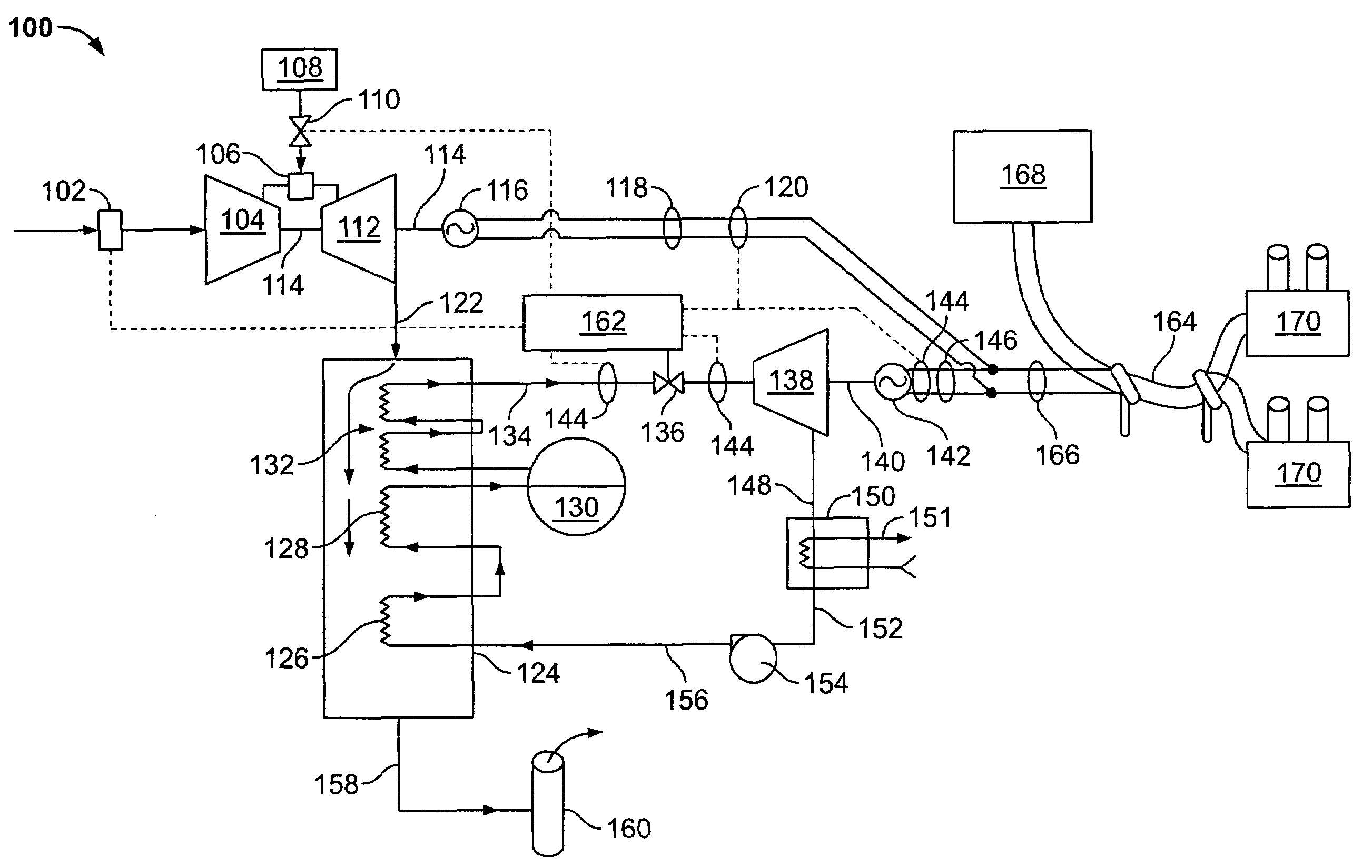
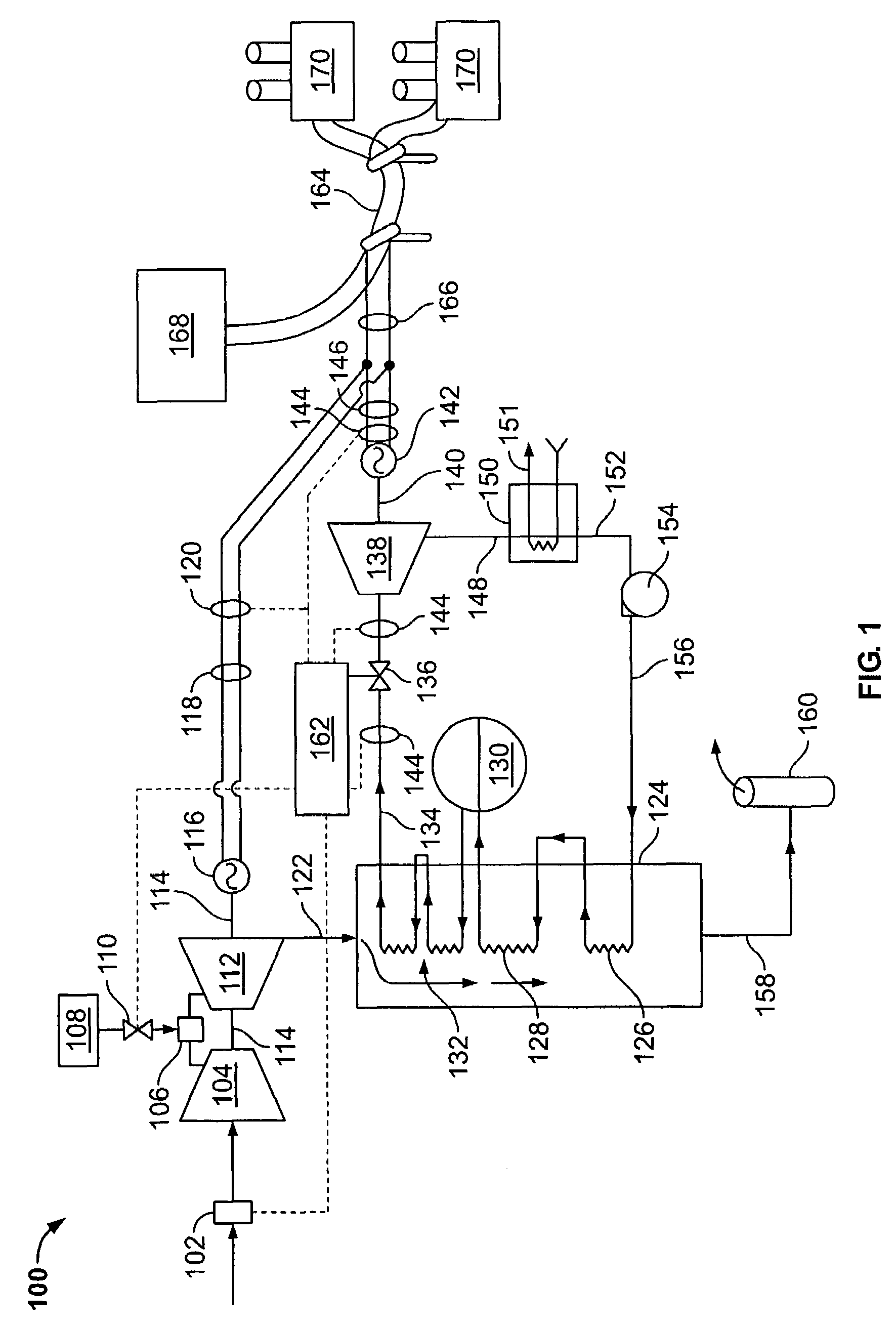
[0020]FIG. 1 is a schematic illustration of an exemplary combined-cycle power generation system 100. System 100 includes at least one combustion turbine air inlet guide vane 102, a combustion turbine compressor 104 that is in flow communication with at least one combustor 106, a fuel storage facility 108 also in flow communication with combustor 106 via at least one fuel supply valve 110, a combustion turbine 112, a common shaft 114, a combustion turbine generator (CTG) 116 that is rotatably coupled to compressor 104 and turbine 112 via shaft 114, a generator output connection 118, a plurality of CTG sensors 120, and a combustion turbine exhaust gas duct 122 in flow communication with a heat recovery steam generator (HRSG) 124. HRSG 124 includes a first set of tube banks 126, a second set of tube banks 128, a steam drum 130, and a third set of tube banks 132 with tube banks 126, 128, 132 and drum 130 in flow communication with each other. System 100 further includes a superheated st...


PUM


Abstract

A method and apparatus for operating a combined-cycle power system is provided. The system is coupled to an electric power grid. The system includes at least one electric power generator, at least one steam turbine coupled to the generator, at least one combustion turbine coupled to the generator, and at least one steam source that is in flow communication with the steam turbine. The method includes operating the system at a first power output level with the steam turbine and the combustion turbine being synchronized to an operating frequency of the grid, so that the steam turbine, the combustion turbine, and the grid are operating at a frequency substantially similar to a standardized grid frequency value. The method also includes sensing a grid frequency deviation away from the standardized grid frequency value. The method further includes accelerating or decelerating the turbines and facilitating a predetermined rate of grid frequency recovery for a predetermined period of time, such that the predetermined rate of frequency recovery is substantially uniform.

Description

BACKGROUND OF THE INVENTION[0001]This invention relates generally to electric power grids and more particularly, to methods and apparatus for operating combined-cycle power systems.[0002]The term “full load” is used herein interchangeably with “rated output” and “maximum continuous rating” (MCR). These terms refer to an upper range of continuous operation output for the power system and its associated components. “Partial load” refers to an output level below full load.[0003]Electric power grids typically include a number of power generating systems to supply electricity to the grid and a number of electricity consumers that draw electricity from the grid. When the generation and consumption of electricity are substantially equal, the grid frequency is substantially constant. Grid frequency is normally a parameter maintained at a substantially stable value. Examples of nominal standard grid frequencies for the European and North American systems are 50 Hz and 60 Hz, respectively.[00...

Claims


Application Information

Patent Timeline
Patent Type & Authority Patents(United States)
IPC IPC(8): H02P9/04F02C6/00
CPCF01D15/10F01D17/16F01K3/00F01K23/101F02C6/14F02C6/18Y02E20/18F05D2220/72Y02E20/16
Inventor ANDREW, PHILIP LYNNFORD, JOHN EDWARDMELSERT, TIMOTHY ANDREW
Owner GE INFRASTRUCTURE TECH INT LLC
Learn More