
Closed loop embedded audio transmission line technology for loudspeaker enclosures and systems

a transmission line and enclosure technology, applied in the direction of transducer details, electrical apparatus casings/cabinets/drawers, cabinets, etc., can solve the problems of limited and ambiguous sound output, inability to provide driver loading of transmission lines, and rather large dimensions typically required, so as to achieve effective implementation of transmission lines, improve reproduction quality, and infinitely dissipate loading

Active Publication Date: 2007-04-24
TBI AUDIO SYST
View PDF14 Cites 21 Cited by
  • Summary
  • Abstract
  • Description
  • Claims
  • Application Information

AI Technical Summary

Benefits of technology

[0008]The proposed invention relates to loudspeakers and in particular methods of improving the quality of reproduction for very low, low, middle and higher frequencies, reducing the relative enclosure dimensions, reducing the costs and dependency on the rooms' acoustics for consistent results. The improvements reflect on a manner of enclosing the driver that frees it from dependence on its' general ambient acoustic environment and allows small drivers of essentially the same diameter to function as full range units or subwoofer units that operate with full range units primarily to extend the response into the lowest registers of the frequency spectrum. Although this applications' focus is on smaller speaker units this technique applies to large-scale bass, full range or sub-bass sound reproduction applications to enhance the larger drivers performance as well. Focus on operation in the sub-bass range generally involves using a port or horn to reduce the motion of the diaphragm near the maximum low frequency output range. Larger drivers will produce more low bass with less diaphragm motion but will be less favorable for direct radiating full range operation because of limited high frequency capabilities. Low frequencies can be directly radiated or radiated through a port or horn coupling for larger drivers. The EAL maintains a constant enclosure pressure over the full frequency range and any volume displacement that can't occupy the line results in greater displacement of the drivers' diaphragm. This results when long wavelength signals stimulate the EATL creating beneficial standing waves to load the driver diaphragm. All wavelengths exist at some finite length within the line as partial or complete as dictated by the variable dynamic air density. Any pressure stimuli will cause a dynamic molecular disturbance within the EATL that creates desirable standing waves that displace the diaphragm with greater ease and accuracy than the signal alone. This enhanced physical displacement is both created by and is the result of the drivers' stimulation by the electrical source plus the dynamic standing wave pattern established within the EATL. This predictable internal loading pattern takes precedent over all other external driver diaphragm stimuli providing critical damping, optimal loading and resistance to room reflections.

Problems solved by technology

It has been determined that an open line although somewhat beneficial would only allow for limited and ambiguous sound output.
This type of line is defined as a Closed Loop Embedded Acoustic Transmission Line (EATL) and does not provide an exit path into the ambient for the wave.
The rather larger dimensions typically required don't providing loading of the driver to sub-bass frequencies.
It is argued in some enthusiasts circles that a transmission line for loudspeakers have infinitely dissipative loading and not assisting the main driver in any way to add or subtract from the output at the diaphragm.
Larger drivers will produce more low bass with less diaphragm motion but will be less favorable for direct radiating full range operation because of limited high frequency capabilities.
The EAL maintains a constant enclosure pressure over the full frequency range and any volume displacement that can't occupy the line results in greater displacement of the drivers' diaphragm.

Method used


Image

  • Closed loop embedded audio transmission line technology for loudspeaker enclosures and systems
  • Closed loop embedded audio transmission line technology for loudspeaker enclosures and systems
  • Closed loop embedded audio transmission line technology for loudspeaker enclosures and systems

Examples


Embodiment Construction

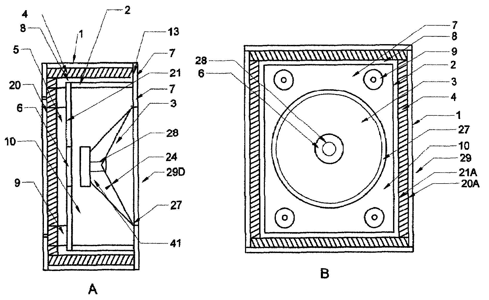
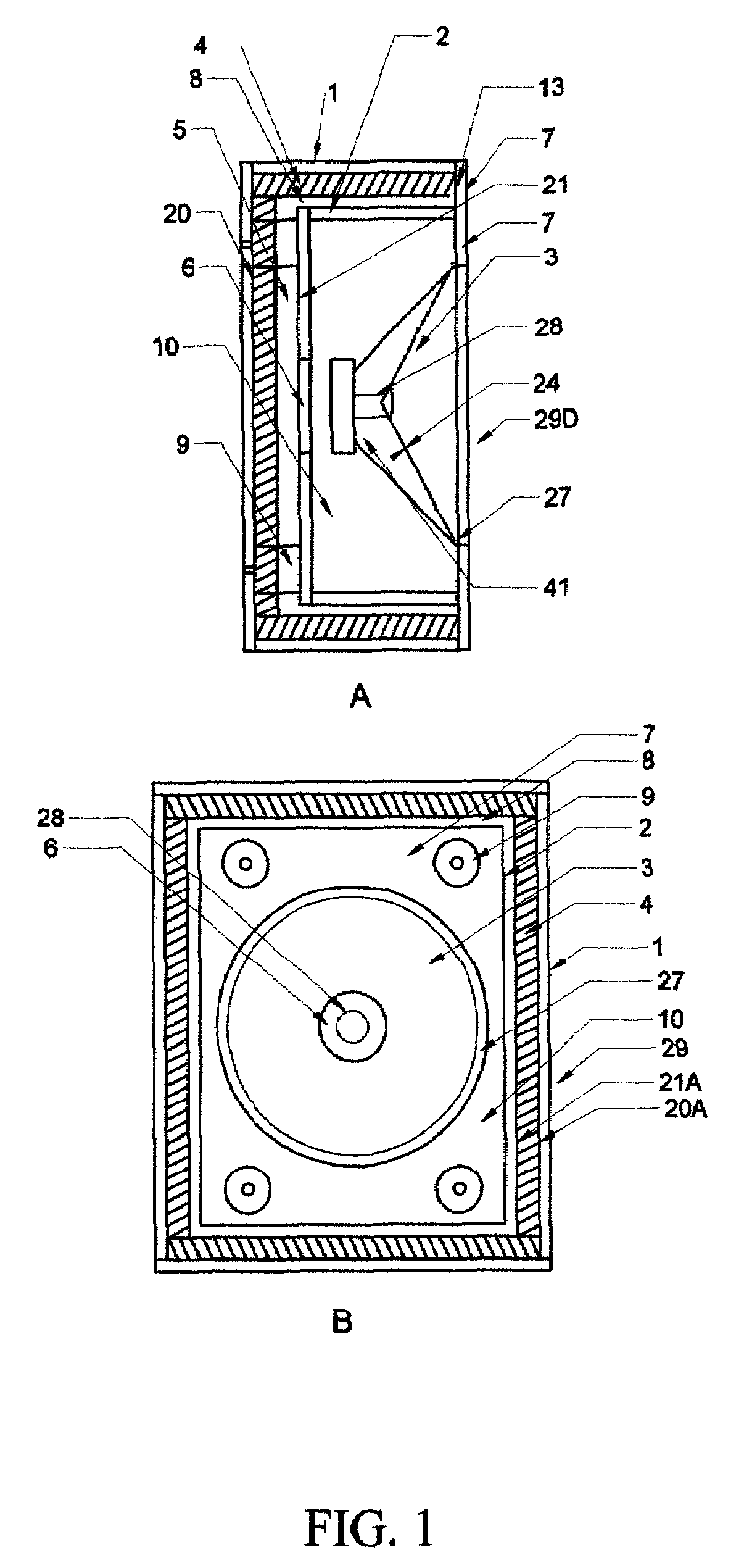
[0025]Throughout this document there will be references to particular items, figures, names, phrases and notable words. The items will appear written once with a bold Capital introductory letter and then abbreviated in the bold letters representing the name in text following. The capitalized bold first letter ('s) and abbreviation may appear subsequently to refresh the memory. Some important statements may be underscored for recognition purposes. Certain terms that may also have an importance in this document but are not pertaining directly to a feature of the document and will not be highlighted or underscored in this mode. FIG. 1 represents a preferred embodiment of the subject invention. FIG. 1A and FIG. 1B represent a complete Direct Radiator Enclosure (DRE) 29D speaker assembly constructed according to this invention. Bernoulli's theorem for the flow of liquid plainly states that a pressure differential must exist for a fluid to flow from a container through a discharge opening...


PUM


Abstract

An acoustic impedance matching enclosure is provided having a driver loaded into a chamber buffering the throat / mouth of a closed loop transmission line. Transmission line consists of a termination member, outer and inner enclosure walls, high-density lining and throat / mouth area. Transmission line eliminates internal random standing waves while providing variable-frequency standing waves that through superposition of the waves compensates for mass-acceleration loss of the high-end of the driver output while damping the resonance of the driver. Alternative application of the acoustic impedance matching enclosure is that of compression loading the driver directly into the closed loop transmission line and using an acoustic low pass filter to translate the output into low frequencies only through a port. Both applications of the acoustic impedance matching enclosure are to insure that the drivers' diaphragm is clear of disruptive internal standing waves, properly loaded at all frequencies and not easily affected by room reflections.

Description

BACKGROUND OF INVENTION[0001]Loudspeakers are a part of everyday life and used for consumer, commercial, military and research applications. The typical loudspeaker is an electro-dynamic transducer and has a diaphragm of some depth and diameter or shape. Electro-dynamic describes a transducer that moves in a positive and negative direction in response to a alternating voltage source to stimulate adjacent air molecules. At this point in time loudspeakers of this type are considered a commodity and are cheap and plentiful in supply. They are typically always mounted on a baffle as part of an existing product or structure; in some form of housing for practical containment or in some cases a form of specialized enclosure is utilized to enhance the bass performance. There are other types of electro-mechanical transducers in use generally exotic but most of which will benefit from the use of the Embedded Transmission Line Technology.[0002]One of the greatest problems is the inherent natur...

Claims


Application Information

Patent Timeline
Patent Type & Authority Patents(United States)
IPC IPC(8): H05K5/00H04R1/02H04R1/28H04R1/38A47B81/06
CPCH04R1/2857H04R1/2819H04R1/2834H04R1/2842H04R1/30
Inventor PLUMMER, JAN PRINCETON
Owner TBI AUDIO SYST
Learn More