
Superconducting device with a cooling-unit cold head thermally coupled to a rotating superconductive winding

Inactive Publication Date: 2007-04-24
SIEMENS AG
View PDF15 Cites 16 Cited by
  • Summary
  • Abstract
  • Description
  • Claims
  • Application Information

AI Technical Summary

Benefits of technology

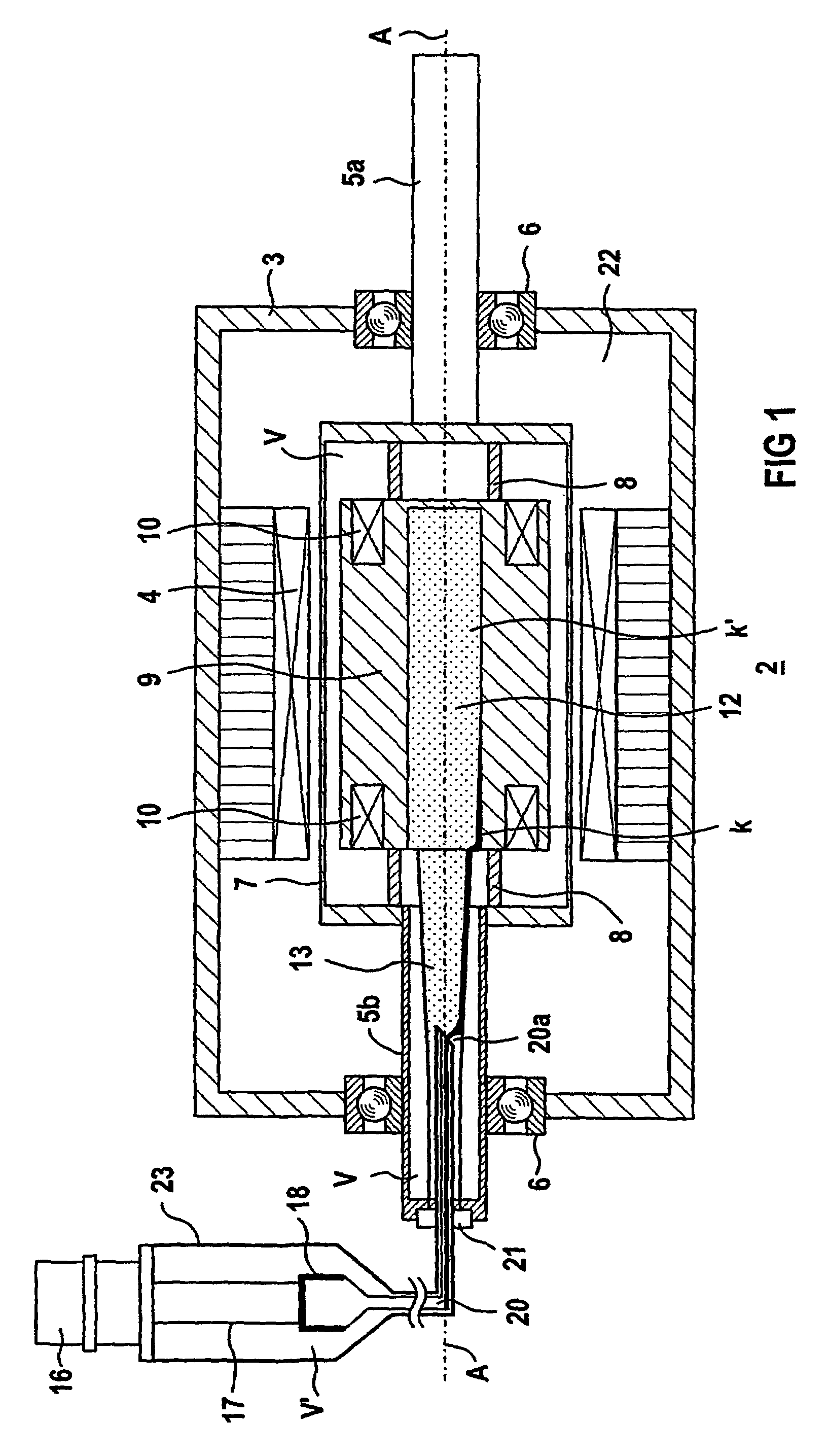
[0014]The advantages of this refinement are, inter alia, that there is no need for any moving parts, such as fans or pumps, to circulate the refrigerant. Furthermore, only a single thermally insulating heat (transport) pipe, which can be designed to be relatively thin, is required to circulate the refrigerant. This reduces the complexity, particularly of the rotating seal, which seals the gas area of the refrigerant from the external area of the rotor. A seal, which is thus only comparatively small, is more reliable and requires less servicing since its circumferential speed is lower. In this case, gas losses of the refrigerant from the internal area to the external area have no significant influence on the operation of the heat pipe, since the amount of liquid in the system is effected only to a minor extent. In consequence, long lives can be achieved with an adequate reservoir size. Furthermore, the refrigeration unit can easily be matched to the different requirements of machine installation. In particular, depending on the configuration, a heat pipe with a length of many meters can be provided so that, for example, a refrigeration machine can be installed at an accessible point in order to simplify its servicing, while the actual motor or generator is installed in a location where access is difficult. The heat transfer and the provision of the refrigeration power are thus particularly simple and economic with the refinement, in particular since only a comparatively simple seal is required.
[0015]It is thus possible to seal the refrigerant area in a particularly simple manner, such that the central cavity is closed on one side by the winding mount, and the lateral cavity is sealed on the side facing the cold head by a sealing device with rotating parts. In this case, at least one seal from the group of ferro fluid seals, labyrinth seals, gap seals may be used as the sealing device.
[0017]The cold head can particularly advantageously be designed to have two or more stages. In particular, parts of an electricity supply or a thermal radiation shield can then in particular be kept at a comparatively high intermediate temperature by its first stage. An appropriately designed cold head thus allows stationary parts of the superconducting device in each case to be kept at a temperature level which is advantageous for effective cooling, in a simple manner.
[0019]It is also advantageous for the heat pipe to be formed as a dripping edge at its end which projects into the lateral cavity. This makes it easier for the condensate to enter the lateral cavity. The refinement can also be implemented in such a way that the process of the droplets dripping off is assisted by rotation, by the gas movement in the rotating internal area resulting from the wind formed by the gaseous part of the refrigerant.
[0020]Furthermore, it may be regarded as being advantageous for the lateral cavity to widen in the direction of the central cavity. This is because it may also be possible to make use of the force of gravity or centrifugal force to assist the transport of the refrigerant, with the transport route of the refrigerant thus being inclined such that it points outward with respect to the rotation axis.

Problems solved by technology

Furthermore, only a single thermally insulating heat (transport) pipe, which can be designed to be relatively thin, is required to circulate the refrigerant.

Method used


Image

  • Superconducting device with a cooling-unit cold head thermally coupled to a rotating superconductive winding
  • Superconducting device with a cooling-unit cold head thermally coupled to a rotating superconductive winding
  • Superconducting device with a cooling-unit cold head thermally coupled to a rotating superconductive winding

Examples


Embodiment Construction

[0024]Reference will now be made in detail to the preferred embodiments of the present invention, examples of which are illustrated in the accompanying drawings, wherein like reference numerals refer to like elements throughout.

[0025]In this case, corresponding parts are provided with the same reference symbols in the figures.

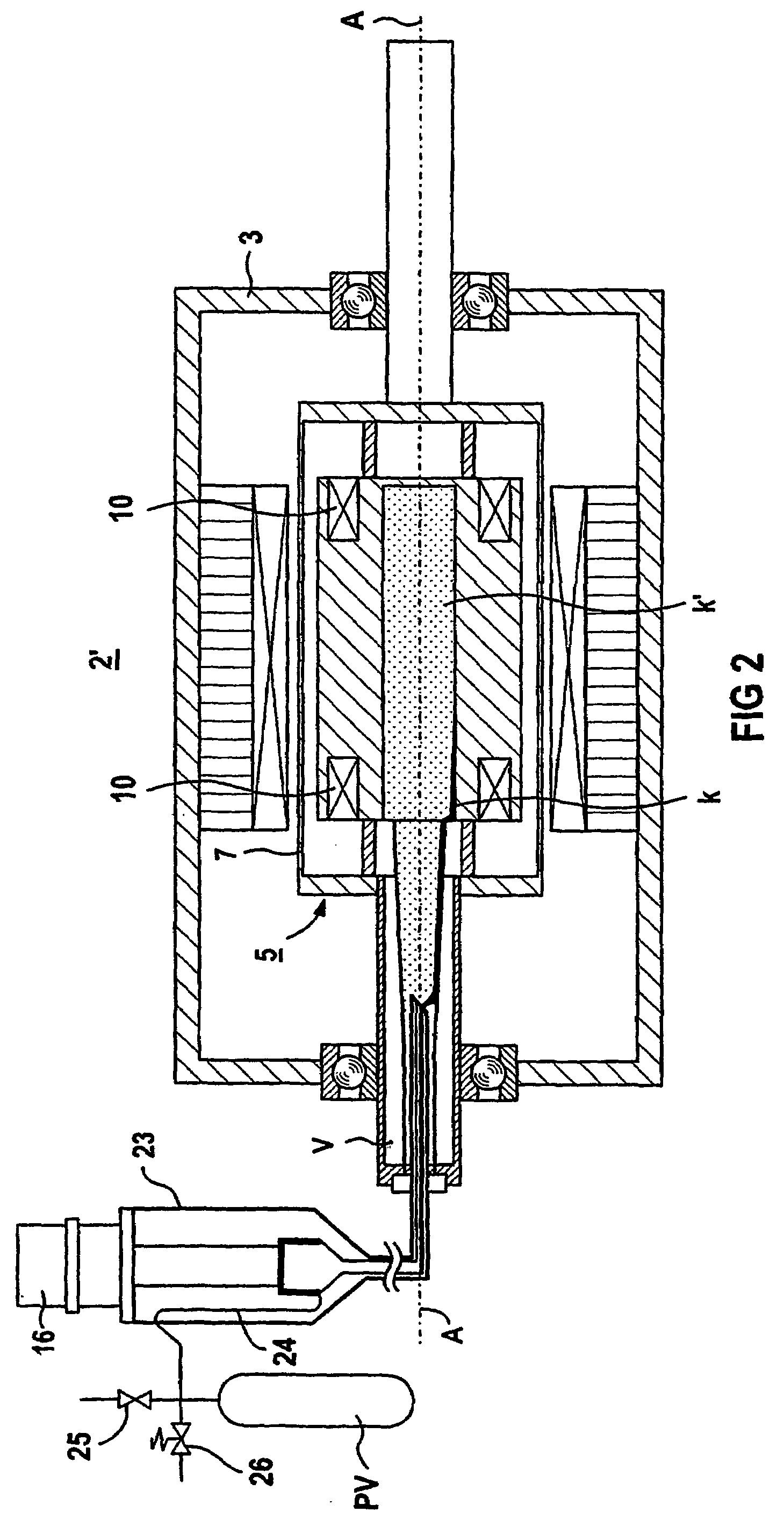
[0026]The embodiments of superconducting devices described in the following text with reference to the figures may each in particular relate to a synchronous motor or a generator. The superconducting device has a rotating, superconducting winding, which in principle allows the use of metallic LTS material (low-Tc superconductor material) or oxidic HTS material (high-Tc superconductor material). The following exemplary embodiments assume that the latter material has been chosen. The winding may comprise a coil or a system of coils in a 2-pole, 4-pole or other multipole arrangement. The basic configuration of a superconducting device such as this which, for examp...


PUM


Abstract

The superconducting device has a rotor which is rotatable about an axis of rotation and is provided with a superconductive winding in a heat conducting winding carrier. The winding carrier has a central cooling agent cavity with a lateral cavity leading out of the winding carrier connected thereto. A cold head associated with a cooling unit is connected to a condenser unit which condenses the cooling agent. A fixed heat tube guiding the cooling agent is coupled to the condenser unit, protruding axially into the coorotating lateral cavity and is sealed in relation thereto.

Description

CROSS REFERENCE TO RELATED APPLICATIONS[0001]This application is based on and hereby claims priority to PCT Application No. PCT / DE01 / 04265 filed on 14 Nov. 2001 and German Application No. 100 57 664.8 filed on 21 Nov. 2000, the contents of which are hereby incorporated by reference.BACKGROUND OF THE INVENTION[0002]The invention relates to a superconducting device having a rotor which is mounted such that it can rotate about a rotation axis and has at least one superconducting winding, whose conductors are arranged in a winding mount which is designed to be thermally conductive, and having a refrigeration unit which has at least one cold head which is thermally coupled to the winding via parts which conduct heat. A corresponding device is disclosed in U.S. Pat. No. 5,482,919.[0003]In addition to metallic superconductor materials such as NbTi or Nb3Sn which have been known for a long time and have very low critical temperatures Tc and which are therefore also referred to as low Tc sup...

Claims


Application Information

Patent Timeline
IPC IPC(8): F25B9/00F25B19/00F25D23/12H02K9/00F25B25/00F28D15/02H02K9/20H02K9/22H02K55/04
CPCF28D15/0266H02K9/20H02K55/04F25B25/005F25B2400/17Y02E40/625Y10S505/878Y02E40/60H02K9/225
Inventor STEINMEYER, FLORIAN
Owner SIEMENS AG
Learn More