
High resolution digital pulse width modulator for DC-DC voltage converter

a voltage converter and digital pulse width technology, applied in pulse manipulation, pulse technique, instruments, etc., can solve the problems of inability to adapt to the situation, impractical solutions, and inability to meet the requirements of dc-dc voltage converters, and achieve finer granularity and improved digital resolution

Active Publication Date: 2007-04-17
INTERSIL INC
View PDF6 Cites 43 Cited by
  • Summary
  • Abstract
  • Description
  • Claims
  • Application Information

AI Technical Summary

Benefits of technology

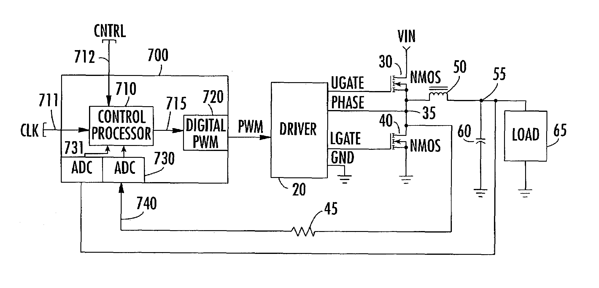
[0026]The truncated fractional bits of the PWM control word do not participate in defining the on-time of the PWM pulse signal of the current pulse, and represent duty-cycle granularity error. The fractional bits are employed as error correction bits in the next cycle of the PWM signal, and prevent the control loop from accumulating a large error in the time average of the PWM generator's output.
[0030]In a second embodiment of the invention, the digital resolution is improved relative to the first embodiment, by making the switching cycle of the PWM pulse signal variable, rather than fixed. Namely, the time between leading edges of PWM pulses, as well as the on-time, is allowed to vary. The result is that the duty-cycle for a given PWM pulse is P / D where both P and D are variable. This refinement in duty-cycle granularity is of particular importance in relatively large voltage step-down applications, where a small duty-cycle (e.g., on the order of 10%) is used to define the on-time of the PWM pulse signal. The ability to change the PWM switching frequency means that differential values of several to ten units, for example, may be added to or subtracted from the denominator's nominal value, to provide finer granularity.

Problems solved by technology

The digital implementation is desirable for all the reasons that have historically favored digital signal processing techniques, but there is a penalty.
The digital PWM granularity imposes performance limitations on the DC-DC regulator in a manner similar to noise in the analog PWM pulse generation.
Unfortunately, both choices obviously result in impractical solutions in light of other system requirements and limitations.
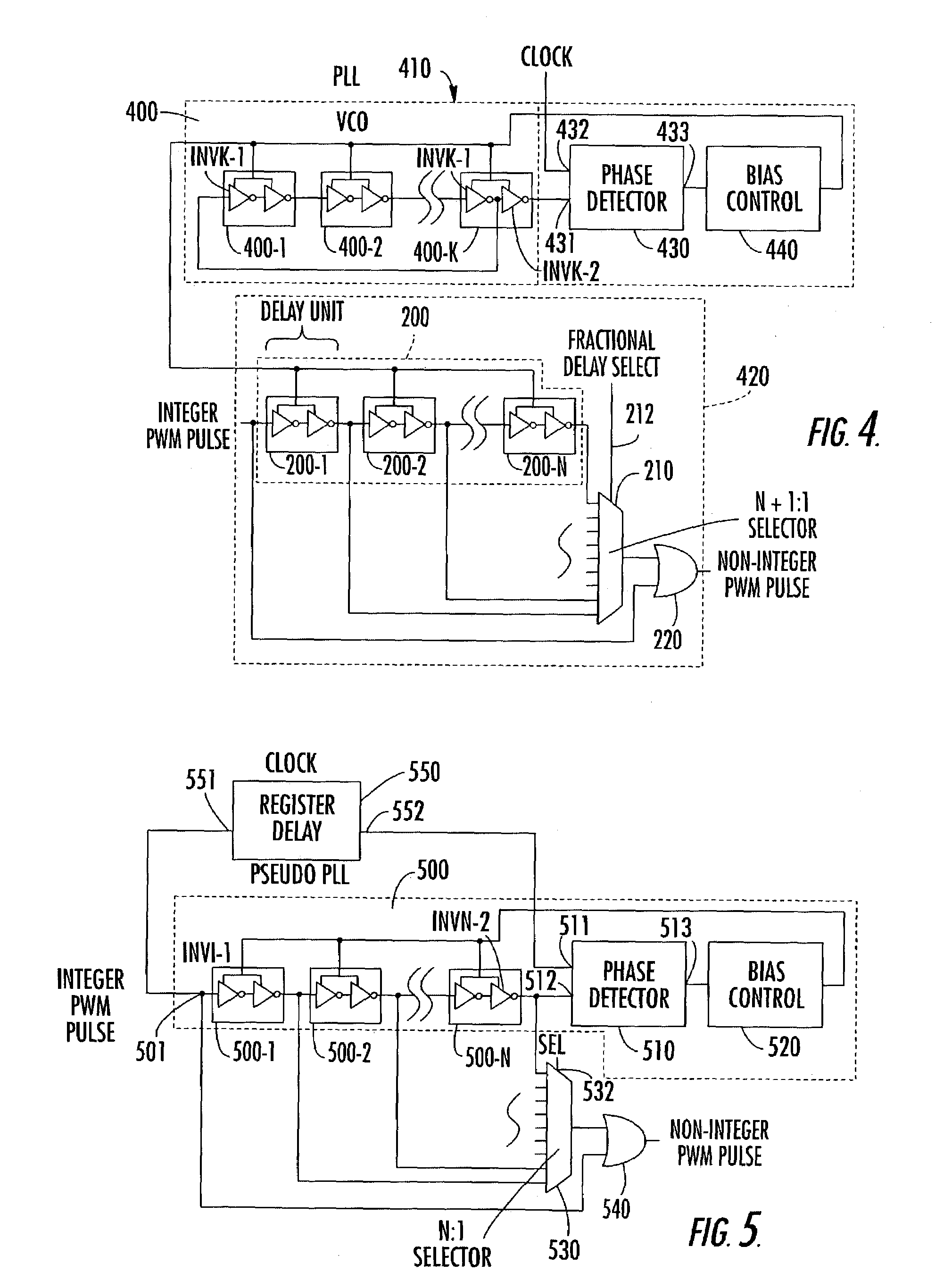
Although the fractional delay scheme of FIG. 2 provides a potentially effective solution to the PWM digital resolution problem, it is limited by a number of practical considerations, such as differences among fabrication runs of its integrated circuit manufacturing process, and operational variations, such as changes in temperature and / or supply voltage.
Moreover, they are not perfectly ‘portable’ among different semiconductor fabrication plants, whose manufacturing parameters can be expected to vary from facility to facility, and therefore require adjustment of the delay line layouts.

Method used


Image

  • High resolution digital pulse width modulator for DC-DC voltage converter
  • High resolution digital pulse width modulator for DC-DC voltage converter
  • High resolution digital pulse width modulator for DC-DC voltage converter

Examples


Embodiment Construction

[0043]Before detailing the high resolution, digital pulse width modulator of the present invention, it should be observed that the invention resides primarily in a prescribed arrangement of conventional digital circuits and components, and associated control software therefor. Consequently, the configuration of such circuits and components and software, and the manner in which they interface with associated analog components have, for the most part, been shown in the drawings by readily understandable block diagrams and flow charts, which show only those specific details that are pertinent to the present invention, so as not to obscure the disclosure with details which will be readily apparent to those skilled in the art having the benefit of the description herein. Thus, the block diagrams and flow charts of the Figures are primarily intended to show the major components of the invention in convenient functional groupings and operational flow sequences, whereby the present inventio...


PUM


Abstract

A digitally-implemented pulse width modulation (PWM) signal generator forms the PWM pulse width as a rational number based on full cycles of a PWM reference clock, and offers a very high effective resolution of the PWM pulse signal that is compatible with multiphase DC-DC converters. Being totally digital allows digital error accumulation and correction to occur at the point of origin of the PWM signal, well upstream of the relatively slow voltage control feedback loop. Quantization errors are corrected before they can accumulate in the converter's DC output voltage.

Description

CROSS-REFERENCE TO RELATED APPLICATION[0001]The present invention relates to subject matter disclosed in co-pending U.S. patent application Ser. No. 10 / 315,836 filed on Dec. 10, 2002, by L. Pearce et al, entitled: “Robust Fractional Clock-Based Pulse Generator for Digital Pulse Width Modulator” (hereinafter referred to as the '836 application), assigned to the assignee of the present application and the disclosure of which is incorporated herein.FIELD OF THE INVENTION[0002]The present invention relates in general to electronic circuits and components therefor, and is particularly directed to a digitally-based pulse width modulator (PWM) circuit, that forms a PWM pulse width as a rational number based on full cycles of a PWM reference clock, so as to provide high resolution digital control of the operation of a DC-DC voltage converter. Digital error accumulation and correction occur at the point of origin of the PWM signal, upstream of the relatively slow output filter and voltage co...

Claims


Application Information

Patent Timeline
IPC IPC(8): H03H7/30H03K5/159H02M3/157H03K5/00H03K5/13H03K7/08H03K9/08H03L7/00
CPCH02M3/157H03K5/133H03K7/08H03L7/00H03K2005/00058
Inventor PEARCE, LAWRENCE G.
Owner INTERSIL INC
Learn More