
Hostile platform position location utilizing networked communications

a technology of networked communication and platform position, applied in the field of system and method for determining the location of objects, can solve problems such as obvious disadvantages, and achieve the effects of improving survivability, reducing costs, and improving accuracy

Active Publication Date: 2007-04-17
ROCKWELL COLLINS INC
View PDF10 Cites 60 Cited by
  • Summary
  • Abstract
  • Description
  • Claims
  • Application Information

AI Technical Summary

Benefits of technology

[0009]A primary advantage of the present invention is derived from the need to conduct communications using dynamic networking protocols. This communication is essential to provide accurate and timely Situational Awareness Communications (SAC). Because the radios must communicate anyway, by utilizing their transmissions not only to provide SAC, but by realizing that the battlefield is being illuminated, the reflections of the SAC can be analyzed by all the friendly battlefield participants to derive the positions of other non-network participants (presumably hostile, because they are not in the network).
[0010]The advantage of legacy and current art using microwave radar is that much greater precision is possible. The disadvantage is obvious. Most fighting vehicles, (e.g. Bradley, Abrams, Paladin, HMMWV, etc) are not equipped with search radar and will likely never be. However, they are and will continue to be, equipped for SA communications. The present invention provides the ability to use the required communications to derive radar like data, provides increased survivability, is relatively low cost and is relatively small size—all benefits to the warfighter.
[0011]The present invention may be used for both ground-based applications and airborne platforms. It can be utilized with forward dismounted network participants such as Land Warrior. Also, the innovation is not frequency specific although certain frequencies will have obvious reflection resolution advantages over others. The principles herein have numerous applications outside of the battlefield. For example, it can be utilized for airborne drug traffic interdiction. Because legitimate flights have a flight plan, the discovery of flights without registered flight plans would warrant direct investigation. This innovation would differ from conventional art that use direct radar illumination (that potentially alerts the suspect) because it is able to exploit the reflections of whatever signals are already available in the spectrum in the region of operation. An example might be using multiple receivers at separate locations receiving the reflections from commercial high powered FM transmissions in Miami, Fla. bouncing off aircraft approaching landfall. This data would be processed to derive an air traffic picture, compared against the ATC expected traffic, and interdiction action taken for the exceptions.
[0012]Although the present invention is computationally intensive it is quite viable with the fielding of the Wideband Networking Waveform and high throughput processing of JTRS radios.

Problems solved by technology

The disadvantage is obvious.

Method used


Image

  • Hostile platform position location utilizing networked communications
  • Hostile platform position location utilizing networked communications
  • Hostile platform position location utilizing networked communications

Examples


Embodiment Construction

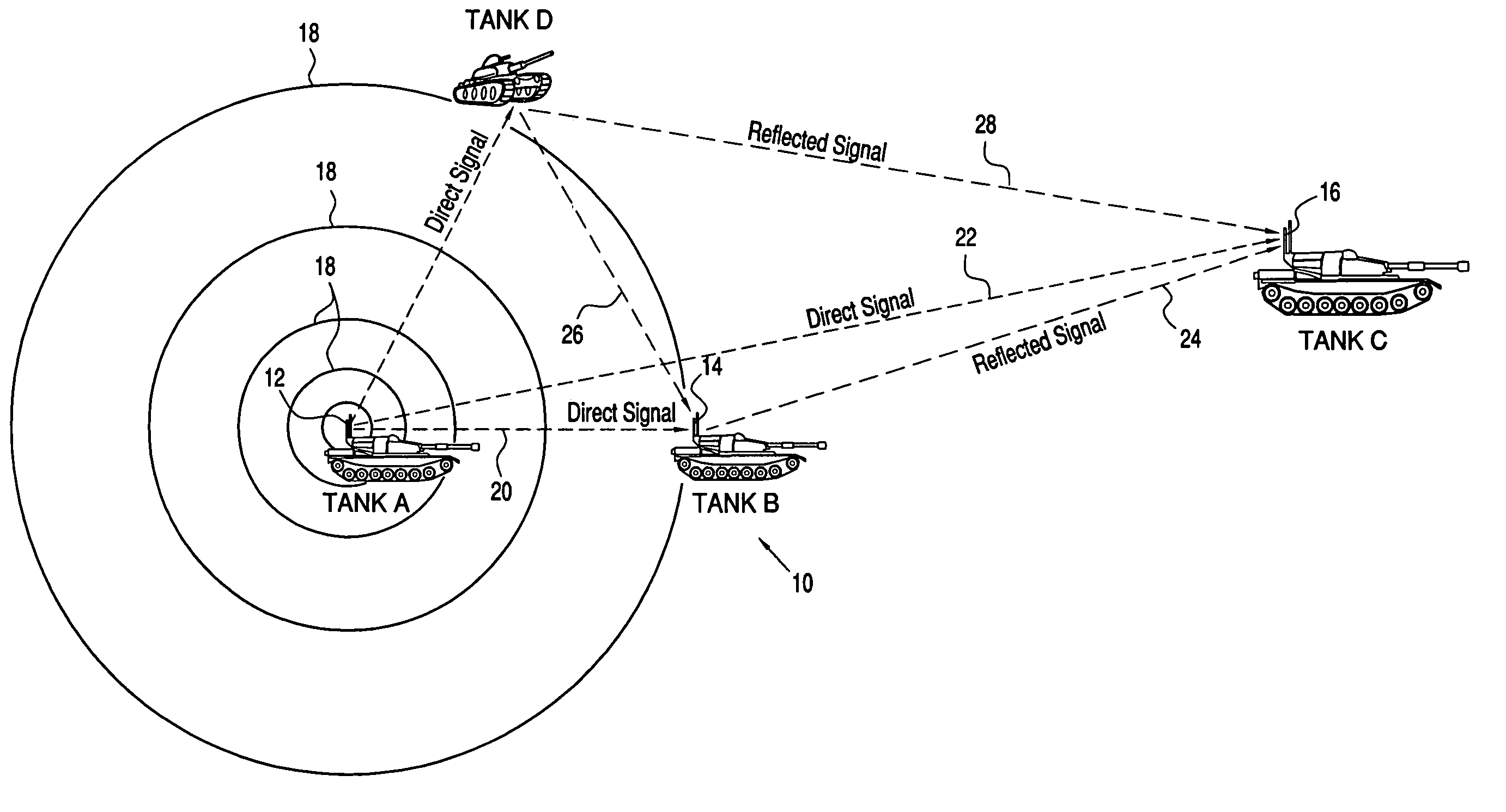
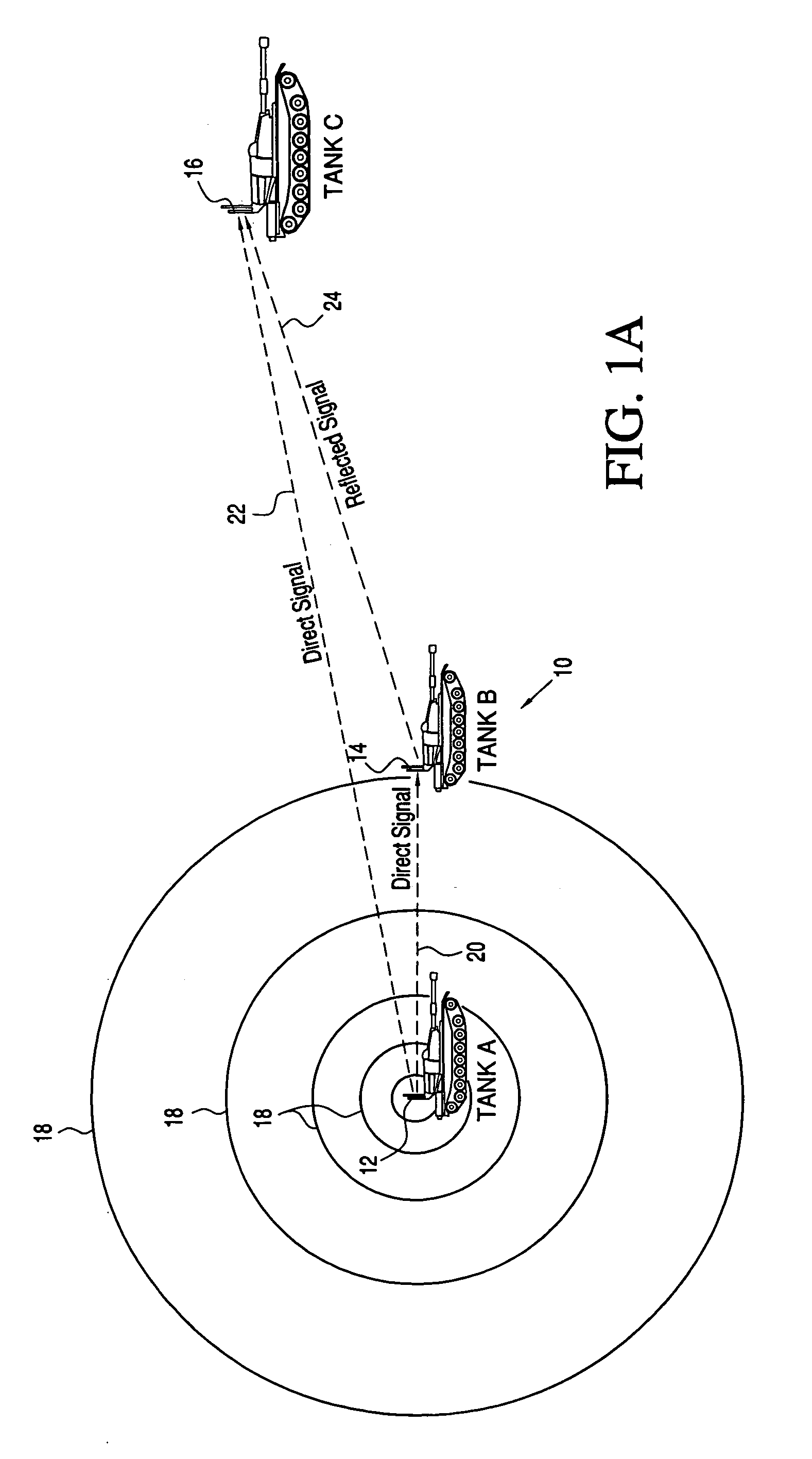
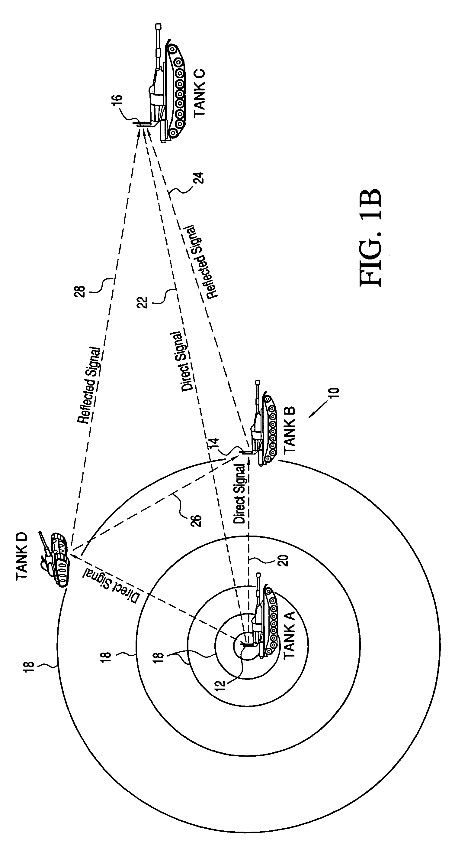
[0015]Referring now to the drawings and the characters of reference marked thereon, FIG. 1 illustrates a digital battlefield 10 utilizing the communication system of the present invention. The communication system includes a plurality of transmitter / receiver units 12, 14, 16 which are positioned on known objects, i.e. Tanks A, B and C, respectively. Each transmitter / receiver 12, 14, 16 has a transmission range in three dimensions as illustrated by concentric circles 18. Deterministic data is transmitted. Deterministic data has distinctive characteristics that make it easily detectable and is distinctive from the vast bulk of data being received. This data is typically a digital “phrase” or sequence that is sufficiently long so as to be statistically significantly “unique” for the confidence required (e.g. 1 occurrence in ten million).

[0016]For the purposes of illustration assume that Tank A originates a single transmission. Tank B receives it first, as shown by direct signal 20. Tan...


PUM


Abstract

The communication system utilizes transmitters that provide communication transmissions having deterministic data. Receivers of the system have the digital processing capability for correlating received transmission reflections of the deterministic data amongst the receivers, the reflections of the deterministic data being from objects within the transmission range of a respective transmitter. The correlating includes utilizing relatively weak multipath signals of the transmission reflections and the superimposition of external data therewith to provide a resulting data base of range reflections. The range reflections are provided to others of said plurality of receivers for processing to derive the environment and the locations and movements of objects without the use of a specific interrogation signal, thereby providing situational awareness.

Description

BACKGROUND OF THE INVENTION[0001]1. Field of the Invention[0002]The present invention relates to systems and methods for determining the locations of objects and more particularly to deriving the environment and the locations and movements of objects without the use of a specific interrogation signal, thereby providing situational awareness.[0003]2. Description of the Related Art[0004]There is an attempt to increase the lethality of vehicles of Future Combat Systems, “Objective Force” by the use of speed and agility. This requires thin skinned armor which increases the vulnerability to conventional weapons of all types. To counter this weakness, in present systems the use of Unmanned Ground Sensors (UGS) must be deployed ahead of the Objective Force vehicles to provide them situational awareness of potential enemies. If the UGS cannot be deployed then the Objective Force cannot risk being utilized.[0005]As will be disclosed below the present invention provides for minimizing the dep...

Claims


Application Information

Patent Timeline
Patent Type & Authority Patents(United States)
IPC IPC(8): G01S13/06
CPCG01S13/003
Inventor SNODGRASS, TIMOTHY E.
Owner ROCKWELL COLLINS INC
Learn More