
Systems and methods for translation of signal levels across voltage domains

Inactive Publication Date: 2007-04-17
MICROSEMI STORAGE SOLUTIONS
View PDF8 Cites 52 Cited by
  • Summary
  • Abstract
  • Description
  • Claims
  • Application Information

AI Technical Summary

Benefits of technology

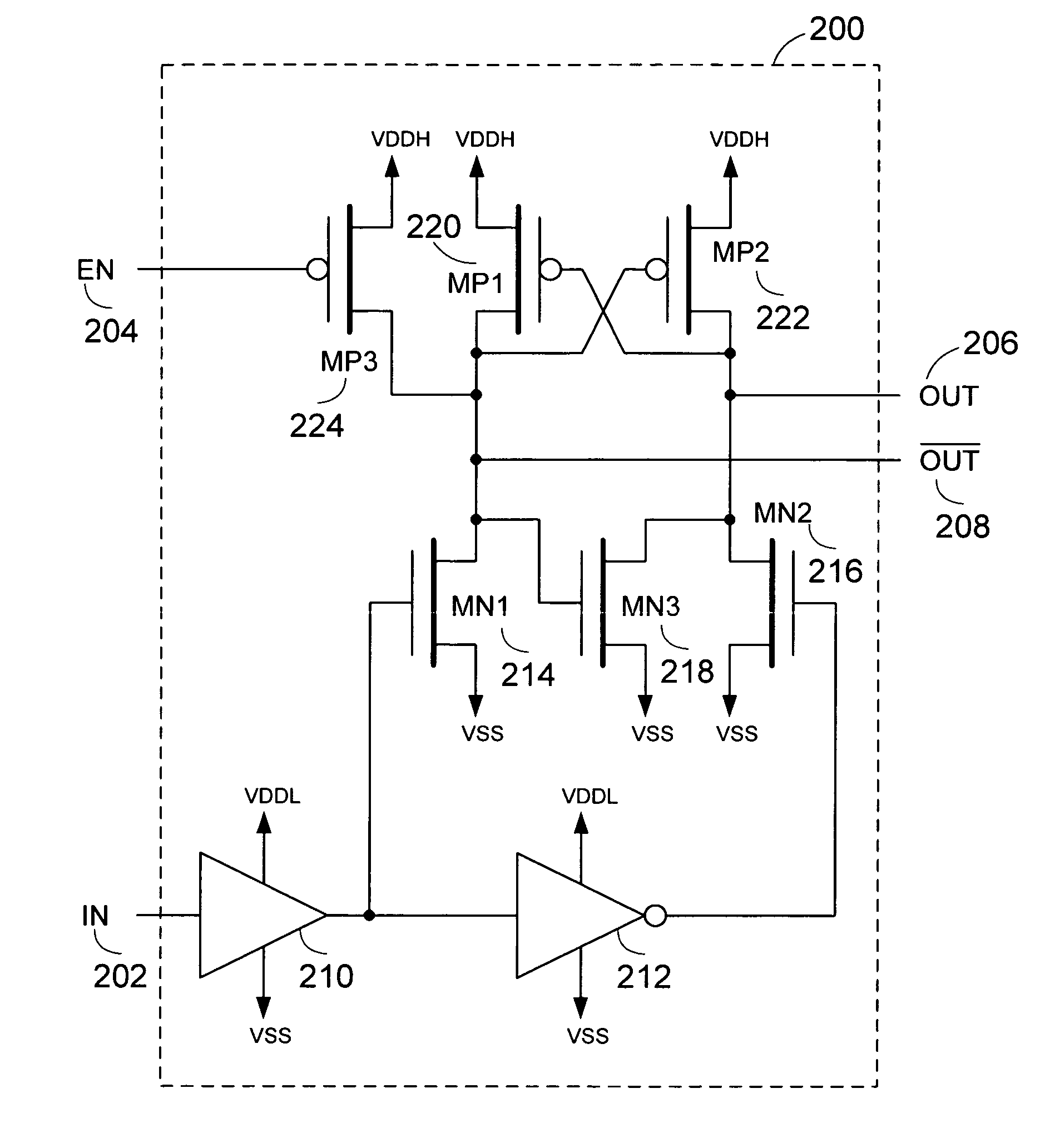
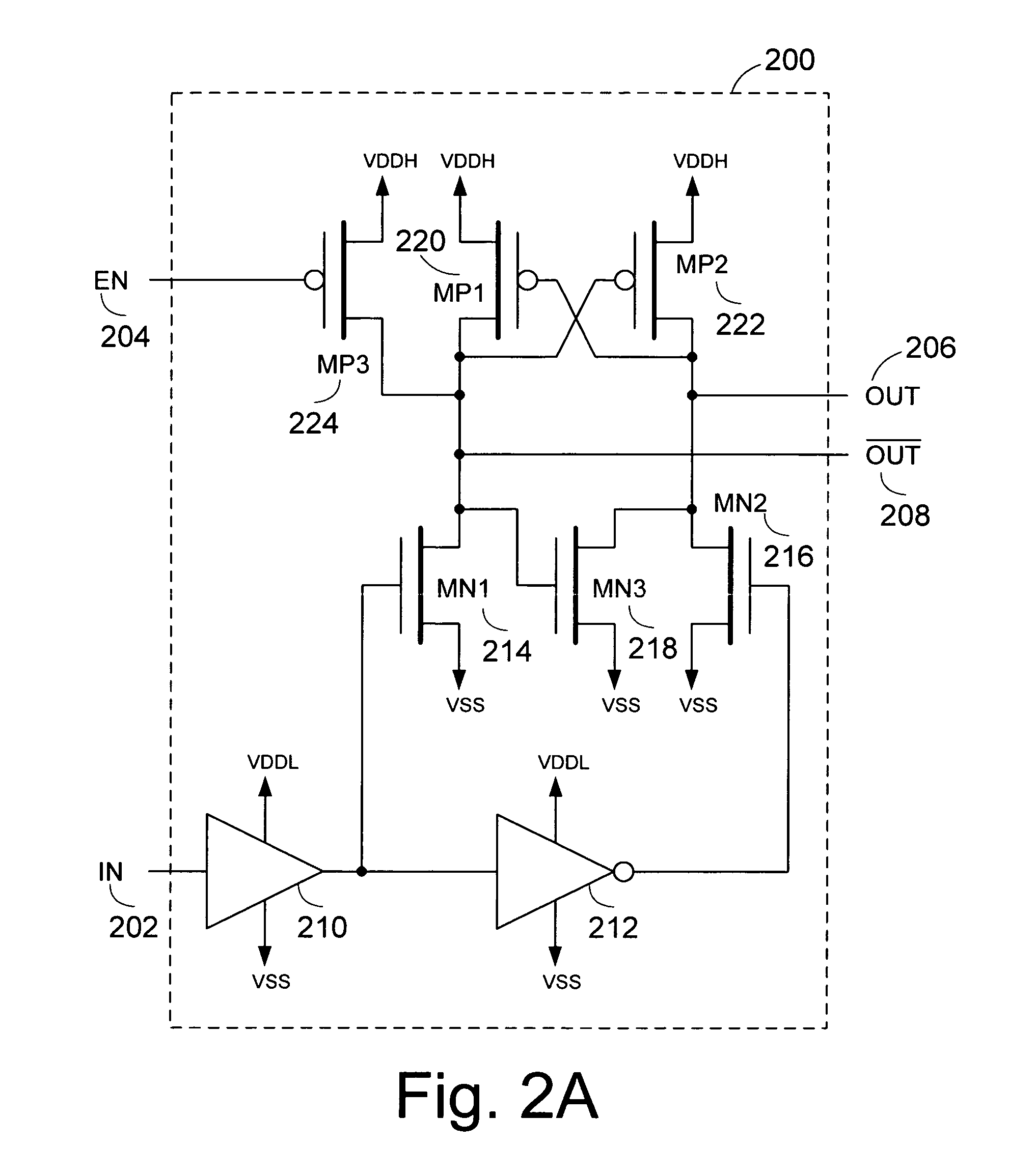
[0010]A level shifting circuit with a power monitor enable for mixed-voltage applications is described. A level shifter translates signals from a first power supply voltage domain to a second power supply voltage domain. The level shifter provides a known output state, rather than a mid-rail state, when either of the power supplies is not adequately powered. In addition, the level shifter is IDDQ (quiescent current) compliant when static, drawing negligible current from the power supply. The level shifter can be used with a power monitor circuit, which con

Problems solved by technology

One challenging aspect for a multiple-voltage integrated circuit is that the sequencing of the multiple power supplies or biases can be unpredictable.
For example, one power supply cannot be guaranteed to power-up before another.
However, due to physical delays in the two sources, either supply could come up slightly before the other.
This can temporarily cause a level-shifter circuit to generate an unknown or unintended output state.
Passing this unknown value can be detrimental to intended circuit performance.
In addition, relatively large on-chip currents can be drawn, potentially damaging the device, if the output of the level-shifter is mid-rail (i.e., between a low level and a high level) or if the level-shifter's unknown state causes contention down-stream.
For example, in a complementary MOS (CMOS) circuit, a mid-rail input can result in mutual conduction from the complementary pairs of transistors, which results in relatively large on-chip currents.
This can disadvantageously prevent the use of IDDQ compliance testing to uncover circuit faults in manufacturing.
Even a relatively small static current can add up to a substantial amount of current when many level shifters are present in a device.
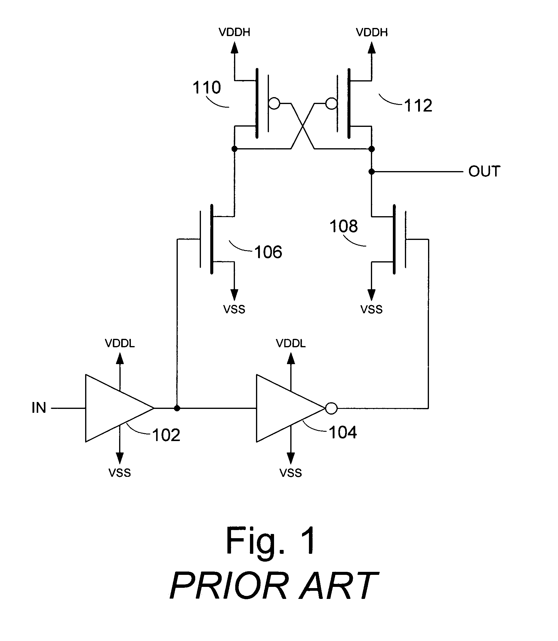
A problem exists when the lower voltage source (VDDL) is not available, and the higher voltage source (VDDH) is ramping up slowly to its normal operating level.
In this circumstance, the level shifter can generate a mid-rail voltage output, which can be damaging to circuits further downstream that are also powered by the higher voltage source (VDDH).
The output (OUT) typically floats “mid-rail” to within a threshold of VDDH, which can lead to harmful mutual conduction and excessive currents in downstream circuitry.

Method used


Image

  • Systems and methods for translation of signal levels across voltage domains
  • Systems and methods for translation of signal levels across voltage domains
  • Systems and methods for translation of signal levels across voltage domains

Examples


Embodiment Construction

[0025]A level-shifter circuit and a power monitor circuit are described. The level-shifter circuit includes an enable control input, which can be used to set the level-shifter circuit at a predetermined state. This can be used to avoid an undefined state, such as a “mid-rail” condition, which can damage devices further downstream of the level-shifter circuit. The presence of such “mid-rail” output conditions plague conventional level-shifter circuits when the lower voltage supply (VDDL) is not available or not fully available, and the higher voltage supply (VDDH) is available. The power monitor circuit controls the enable control input of the level-shifter circuit. In one embodiment, the power monitor circuit is compliant the with quiescent current (IDDQ) testing requirements with a relatively small area.

[0026]While generally described as a “level shifter” in the context of an integrated circuit using two or more voltage biases with at least a lower bias supply (VDDL) and a higher v...


PUM


Abstract

A level shifting circuit with a power monitor enable for mixed-voltage applications is described. The level shifter translates signals from a first power supply voltage domain to a second. The level shifter provides a known output state, rather than an undefined mid-rail state, when either of the power supplies for the voltage domains is not adequately powered. In addition, the level shifter is IDDQ (quiescent current) compliant when static, drawing negligible current from the power supply. The level shifter can be used with a power monitor circuit, which controls the level shifter during power-up with an enable signal.

Description

CROSS-REFERENCE TO RELATED APPLICATION[0001]This application claims the benefit under 35 U.S.C. § 119(e) of U.S. Provisional Application No. 60 / 587,018, filed Jul. 8, 2004, the entirety of which is hereby incorporated by reference.BACKGROUND[0002]1. Field of the Invention[0003]The invention generally relates to integrated circuits that use multiple voltage biases, and in particular, to interface circuitry for translating signals from one voltage domain to another.[0004]2. Description of the Related Art[0005]Many integrated circuits or “chips” employ multiple power supplies or biases. For example, a digital core of a chip may operate from a 1.2V supply, while a low-voltage differential signaling (LVDS) transmitter in an input / output (I / O) portion of the chip may operate from a 3.3V supply. Terms that have been used to describe these integrated circuits include “split-voltage” or “dual-voltage.” This difference in voltage requires an interface to translate data and control signals bet...

Claims


Application Information

Patent Timeline
IPC IPC(8): H03L5/00
CPCH03K3/356165
Inventor YEUNG, SALLYLYE, WILLIAM MICHAEL
Owner MICROSEMI STORAGE SOLUTIONS
Learn More