
Metal gasket

a technology of metal gaskets and gaskets, which is applied in the direction of engine seals, sealing arrangements, machines/engines, etc., can solve the problems of fatigue fracture in the stopper, the ratio of height to width of each wave is so large, and the contact pressure is not balanced around the combustion chamber. to achieve the effect of improving the formability of the stopper, improving the sealing performance, and increasing the circularity of the cylinder hol

Inactive Publication Date: 2007-04-17
HATAMURA KOICHI +1
View PDF16 Cites 28 Cited by
  • Summary
  • Abstract
  • Description
  • Claims
  • Application Information

AI Technical Summary

Benefits of technology

"The present invention provides a metal gasket that can prevent the occurrence of cracks and fatigue fracture in the stopper while using a wave-shaped stopper. The metal gasket has a single-layer or multiple-layer structure, with an inner circumference side stopper formed to enhance fatigue resistance and improve engine performance. The metal gasket has a wave-shaped cross section with alternating thin and thick portions, with the hardness of the thin portions being higher than that of the thick portions. This results in increased fatigue limit and reduced likelihood of crack formation. The metal gasket can be manufactured without the need for a special mold, reducing manufacturing processes and costs. The inner and outer circumference side stoppers can have the same or different height to optimize contact pressure balance. A groove can be formed along a portion where stress amplitude is large to further prevent crack formation."

Problems solved by technology

Formation of a stopper only on the inner circumference side of a bead will lead to a problem of poor balance of contact pressure around a combustion chamber.
It is known that stress amplitude occurs in a metal gasket bead, repeating compression and decompression, due to pressure fluctuation in cylinders of an engine during engine operation, and such stress amplitude constitutes a factor that causes cracks in the bead.
When a plurality of waves with a narrow width (with a short wavelength) are arranged to function as a stopper as described in the Japanese Patent Kokai Publication No. 2004-144119 and Kohyo Publication No. 2004-503731, in particular, the ratio of height to width of each wave is so large that fatigue fracture will possibly occur in the stopper if the waves are formed by a same method as the bead.
More specifically, according to conventional techniques, a bead is formed using a mold having a molding surface substantially conforming to the final shape of the bead, and this fact raises a problem that a large frictional force is generated between the top of a male punch and a blank metal sheet.
This tendency becomes more severe as the ratio of height to width of a bead becomes larger.
Therefore, if waves are formed with a large ratio of height to width as described in Japanese Patent Kokai Publication No. 2004-144119 and Kohyo Publication No. 2004-503731, there is a risk that fatigue fracture occurs at the top of the waves in the stopper.
However, cracks are liable to occur at the tops of waves which are subject to maximum stress amplitude.
This makes the manufacturing process complicated and requires a special mold for the smoothing process.
However, the thermal resistance requirement is particularly stringent to the stopper on the inner circumference side, that is arranged on the side of combustion chamber, and such stopper is subjected to load exerted in the shearing direction due to difference in coefficient of thermal expansion between a cylinder head and a cylinder block.
Therefore, there is a risk that the sealing performance is deteriorated as the result of the stopper coming off.

Method used


Image

  • Metal gasket
  • Metal gasket
  • Metal gasket

Examples


first embodiment

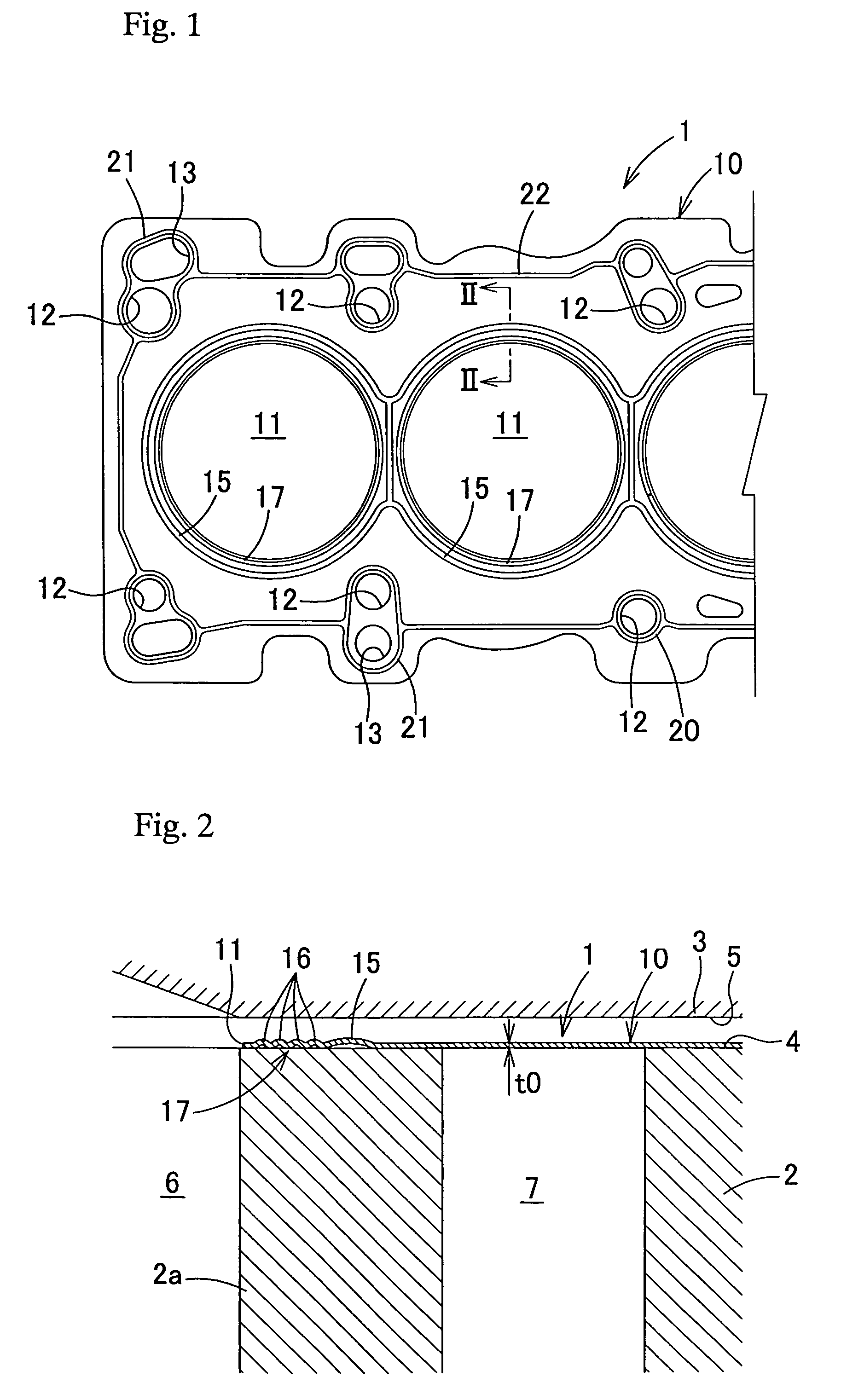
[0057]A metal gasket 1 shown in FIGS. 1 and 2 is a metal gasket for in-line multiple-cylinder engines. This metal gasket 1 is designed to be interposed between joint surfaces 4 and 5 of a cylinder block 2 and a cylinder head 3 to seal the joint surfaces 4 and 5 which face a combustion chamber 6, a water jacket 7, a lubricating oil passage (not shown) and soon. The metal gasket 1 according to the present invention is applicable to engines having a cylinder block of cast iron, and engines having a cylinder block and a cylinder head principally made from a light alloy such as aluminum alloy or magnesium alloy. In this embodiment, the metal gasket 1 according to the present invention is applied to an engine which has an open deck type cylinder block 2 in which the top face of a water jacket 7 is open, and the cylinder block 2 and a cylinder head 3 of which are made from an aluminum alloy.

[0058]The metal gasket 1 is composed of a single gasket component sheet 10 which is interposed betwe...

second embodiment

[0078]As shown in FIGS. 4 and 5, a metal gasket 1A according to this second embodiment is a single layer metal gasket composed of a gasket component sheet 10A, and is constituted by partially modifying the gasket component sheet 10 of the metal gasket 1 of the first embodiment described above. In FIGS. 4 and 5, like components to those of the first embodiment are designated with like reference numerals and description thereof is omitted.

[0079]The gasket component sheet 10A of the metal gasket 1A is provided with an inner circumference side stopper 17A with a wave-shaped cross section having two waves 16, instead of the inner circumference side stopper 17 of the gasket component sheet 10 according to the first embodiment, and is further provided with an outer circumference side stopper 30 with a wave-shaped cross section having two waves 16. The outer circumference side stopper 30 is provided on the outside of and close to the combustion chamber bead 15 so as to surround the entire o...

third embodiment

[0085]Description so far has been made on the first and second embodiments in which the metal gaskets 1, 1A and 1B is constituted by a single gasket component sheet 10, 10A and 10B, respectively. However, the present invention is also applicable to a multiple-layer metal gasket composed of a plurality of gasket component sheets.

[0086]Specifically, FIG. 7A shows a metal gasket 1C, for example, in which a substantially flat gasket component sheet 35 is laid over the surface of the gasket component sheet 10A according to the second embodiment which includes the projecting side of the combustion chamber bead 15. Alternatively, FIG. 7B shows a metal gasket 1D, in which a flat gasket component sheet 35 is laid over the opposite surfaces of the gasket component sheet 10A according to the second embodiment. Yet further alternatively, FIG. 7C shows a metal gasket 1E, in which a gasket component sheet 36 having a combustion chamber bead 15 is laid over the surface of the gasket component shee...


PUM


Abstract

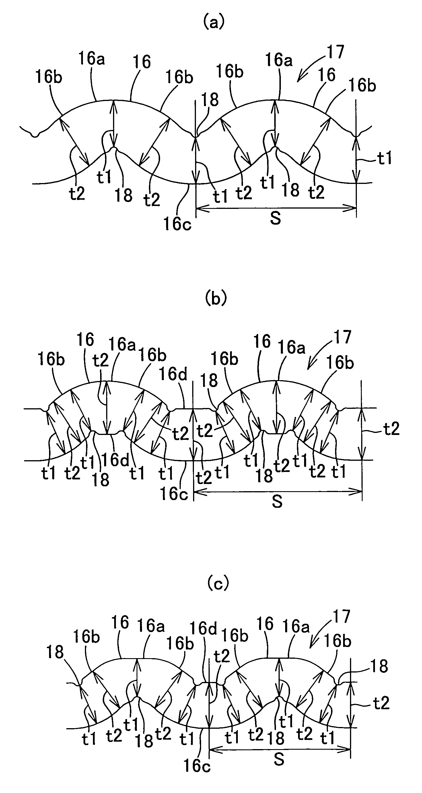
A metal gasket capable of preventing the occurrence of cracks in a stopper while employing a wave-shaped stopper, improving the contact pressure balance around the bead to enhance the engine performance, and improving the durability of the stopper. The metal gasket is constituted by a gasket component sheet having an opening formed to face a combustion chamber, and the gasket component sheet is provided with a combustion chamber bead surrounding the opening. An inner circumference side stopper lower than the height of the combustion chamber bead is formed along the combustion chamber bead in a portion between the combustion chamber bead and the opening such that at least a section of each wave where stress amplitude is large becomes thin, a thin portion and a thick portion are arranged alternately in each wave, and the hardness of the thin portion is higher than that of the thick portion.

Description

BACKGROUND OF THE INVENTION[0001]1. Field of the Invention[0002]The present invention relates to a metal gasket that can be suitably used for automobile engines.[0003]2. Description of the Related Art[0004]A metal gasket widely employed for automobile engines is one which is composed of a single or a plurality of gasket component sheet(s). The gasket component sheet has an opening formed to face a combustion chamber, a bead formed to surround the opening, and a stopper formed on the inner circumference side of the bead to prevent the flattening of the bead.[0005]An example of widely used stoppers is formed by folding back the peripheral edge of a gasket component sheet opening so that this folded part is used as a stopper. Meanwhile, it has recently been proposed, as disclosed in Japanese Patent Kokai Publication No. 2004-144119, to form a stopper with a wave-shaped cross section, by means of press molding, on the inner side of a bead on a gasket component sheet and concentrically w...

Claims


Application Information

Patent Timeline
Patent Type & Authority Patents(United States)
IPC IPC(8): F02F11/00F16J15/08
CPCF16J15/0818F16J15/0825F16J2015/085F16J2015/0856F16J2015/0862F16J2015/0875
Inventor HATAMURA, KOICHISUZUKIOGINO, HIROYUKISUGIURA, TAKAHIKOOKUDAIRA, YASUYUKIWAKUDA, TAKESHIMAHIGASHI, REIJIUMEHARA, KEISUKEKUMASHIRO, MASAHISA
Owner HATAMURA KOICHI
Learn More