
Goods transshipment apparatus

a transshipment apparatus and goods technology, applied in the direction of resilient suspensions, cranes, transportation items, etc., can solve the problems of only being able to drive under its own power to very limited distances, only being used in a very limited way for unloading ships, and having to do maintenance, lubrication, refuelling etc. of the engine compartment integrated in the superstructure, etc., to achieve the effect of increasing the flexibility of the goods transshipment apparatus, facilitating r

Inactive Publication Date: 2007-04-17
FUCHS BAGGER & MASCHFAB
View PDF27 Cites 12 Cited by
  • Summary
  • Abstract
  • Description
  • Claims
  • Application Information

AI Technical Summary

Benefits of technology

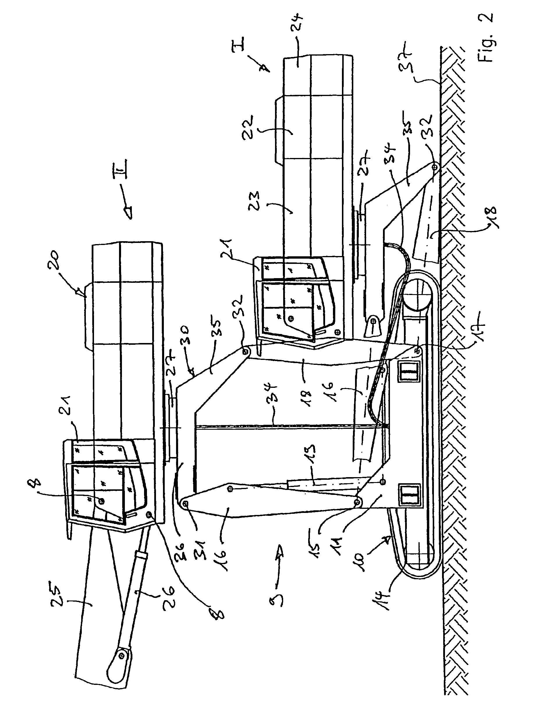
[0006]According to the invention, the superstructure of the goods transshipment apparatus according to the invention is constructed to be moveable between a lower position (resting position) on the substructure and an upper position (operating position) at a spacing from the substructure. This provision according to the invention increases the flexibility of a goods transshipment apparatus, as the adjustment of the position of the superstructure between a lower and an upper position on the one hand ensures that the jib is mounted high enough and thus meets all the requirements of length of reach, loading depth and degree of overload from the sides of ships, while on the other hand in the lowered position on the substructure the inherent mobility is improved and transportation on low-loaders is made possible. Furthermore, maintenance staff can comfortably climb into the driver's cab on the superstructure when it is in the lowered position and the refuelling and maintenance of the engine etc is also made easier in this lowered position.
[0008]Advantageously, the goods transshipment apparatus is constructed so that in the upper position (operating position) a vertical rotation axis of the superstructure extends substantially through the centre of the substructure in the case of an endless track drive or through the centre of the support for the substructure in the case of a wheeled drive, in order to ensure equal stability on all sides during operation, particularly when the superstructure is rotated.
[0010]According to a particularly advantageous embodiment of the invention the superstructure is lowered into the lower position by pivoting the parallel connecting rods towards the rear of the goods transshipment apparatus. As a result the superstructure is lowered into a position in which it comes to rest above the rear part of the goods transshipment apparatus, making it possible to fold in the jib extending towards the front part of the goods transshipment apparatus over the front part of said apparatus and accommodate it there so as to take up the least possible height for the resting and shipping position. It has also proved advantageous for the engine compartment mounted on the superstructure to come to rest in a position located behind the substructure, in which it is directly accessible from several sides, thus making it much easier to carry out maintenance, refuelling and the like.
[0011]According to a further feature of the invention, the parallel connecting rod jointed in the rear part is jointed lower down than the parallel connecting rod jointed in the front area, and the parallel connecting rod jointed in the rear part is jointed to the superstructure on a portion of the subframe of the superstructure which slopes diagonally downwards. The part of the subframe of the superstructure which slopes diagonally downwards follows the geometry of the substructure and is constructed so that in the lowered bottom position of the superstructure, when a front horizontal portion of the subframe abuts or rests on the substructure it extends behind the rear of the substructure to the ground (travel surface) and thus provides maximum support and load relief for the parallel connecting rods. In addition, steps may be formed or provided on the portion of the subframe of the superstructure which extends diagonally downwards, to allow maintenance staff to gain easy access to the superstructure or driver's cab.

Problems solved by technology

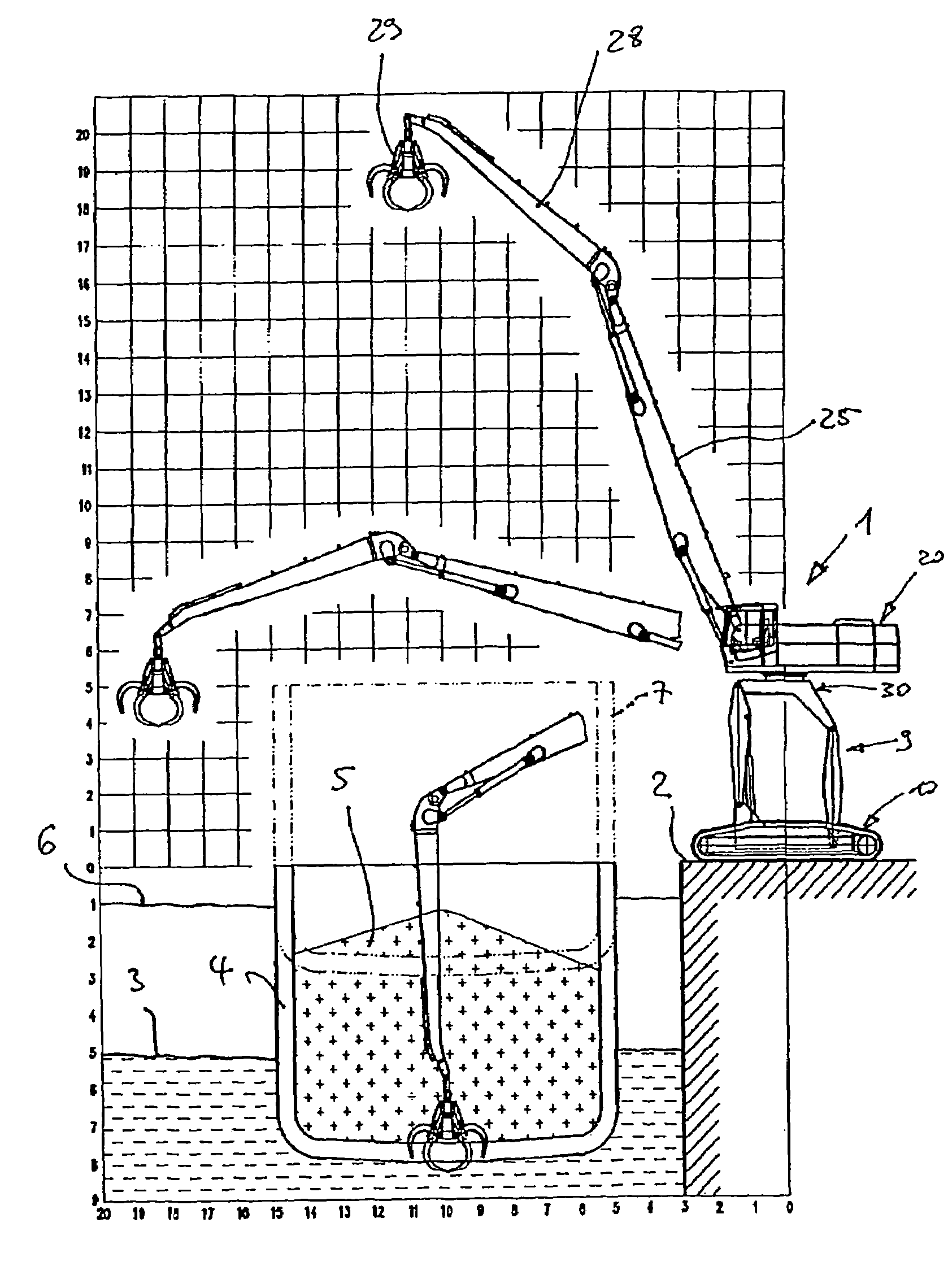
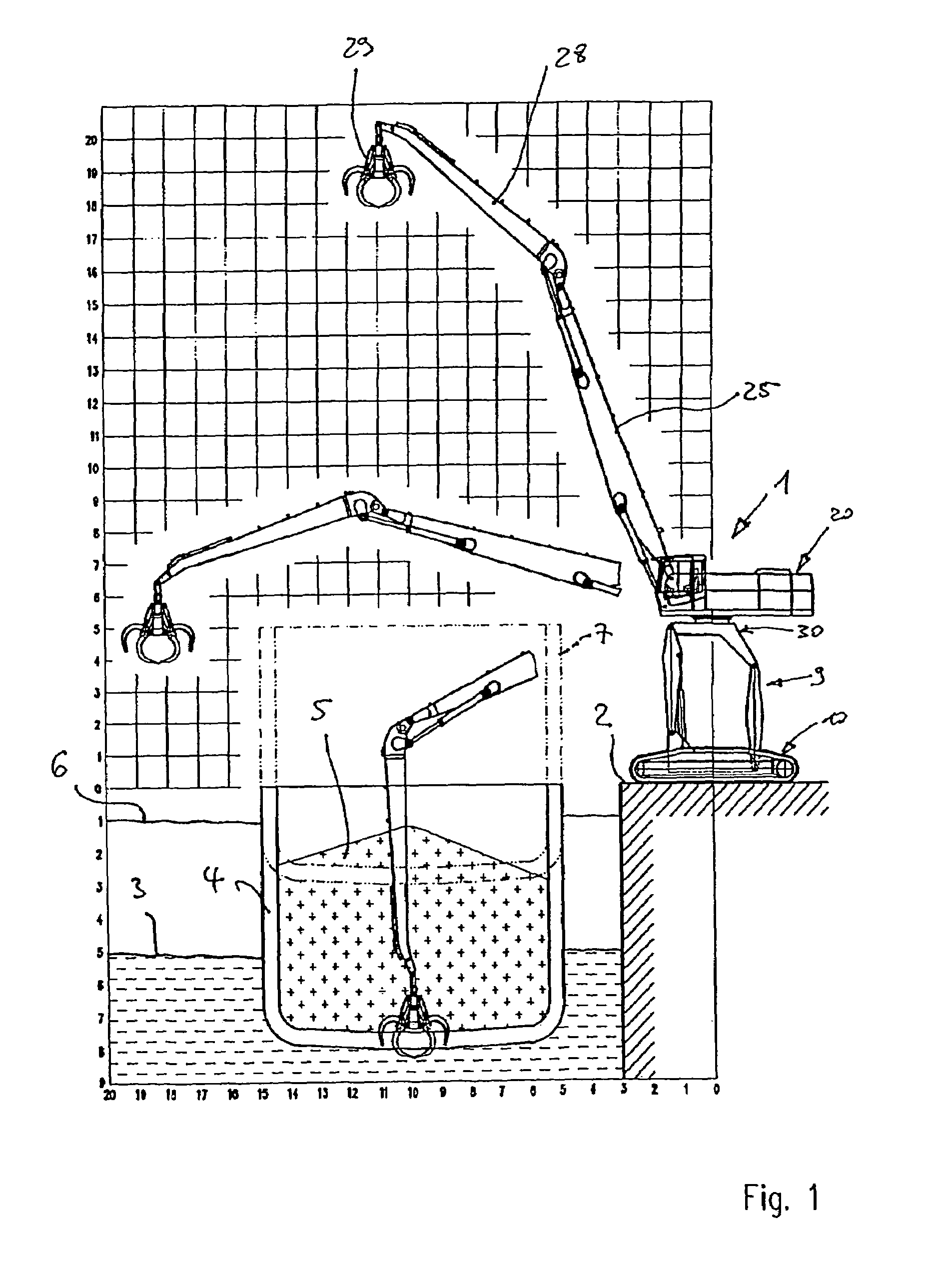
Because of this dimensional restriction, these transshipment apparatus can only be used in a very limited way for unloading ships, as at high water when the ship is almost unloaded the side of the ship may be at a height of about 5 to 6 meters above the quay and the articulation axis of the transshipment apparatus should be at approximately the same height.
This known goods transshipment apparatus is particularly suitable for use in unloading ships in harbour transshipment operations and on building sites, but it does have the disadvantage that it has to be built on site and can only be driven under its own power to very limited distances of not more than 2 to 4 kilometers—provided that there are no bridges, powerlines or the like in the way.
A further disadvantage of this known goods transshipment apparatus is the fact that the maintenance, lubrication, refuelling, etc of the engine compartment integrated in the superstructure has to be done at a height of 4 to 6 meters.

Method used


Image

  • Goods transshipment apparatus
  • Goods transshipment apparatus
  • Goods transshipment apparatus

Examples


Embodiment Construction

[0039]FIG. 1 shows a first embodiment of a goods transshipment apparatus 1 according to the invention. The goods transshipment apparatus a according to the invention (hereinafter referred to ad loading apparatus for short, in the interests of simplicity) comprises a substructure 10 which travels on endless tracks and a superstructure 20. The superstructure 20 comprising a driver's cab 21, an engine compartment 22, a chamber 23 for hydraulics and a tail weight 24 is mounted on a subframe 30 by means of a rotary mounting 27 (cf also FIG. 2 which shows a partial side view of the loading apparatus 1 according to the invention) . Also jointed to the superstructure 20 is a jib 25 with a loading arm 28 and grab 29 on a jib mounting shaft 8. Obviously, it is also possible to use jib systems other than that shown, e.g. having more jib combinations.

[0040]According to the invention, the superstructure 20 is mounted at a height of about 5–6 meters from the substructure 10. This spaced arrangeme...


PUM


Abstract

A goods transshipment apparatus having a mobile substructure with a superstructure mounted so as to be rotatable relative to said substructure and having a driver's cab and engine compartment and a jib or jib system jointed to the superstructure wherein the superstructure is adjustable between a lower position (resting position I) on the substructure and an upper position (operating position II) at a spacing from the substructure.

Description

FIELD OF THE INVENTION[0001]The present invention relates to a goods transshipment apparatus.DESCRIPTION OF THE RELATED ART[0002]Goods transshipment apparatus of this kind, also known as loading or shipping apparatus, are used primarily in inner ports and the adjacent stockyards for transshipping i.e. loading and unloading all kinds of materials such as wood, scrap metal, gravel, sand and the like. Goods transshipment apparatus are high performance flexible loading machines with a long reach (at least 18 to 20 meters) and fast operating cycles using large grabs, magnetic sheets or the like. The requirements imposed on these loading machines in terms of flexibility are connected on the one hand with their use in working at the quayside for unloading ships at both high and low water and on the other hand in rapid transfer of the loading machine to another unloading point or to a stockyard which may even be a fair distance away (10 to 50 km).[0003]Stationary loading machines or docks c...

Claims


Application Information

Patent Timeline
Patent Type & Authority Patents(United States)
IPC IPC(8): B66C23/78B66C23/36B66C23/42B66C23/62B66C23/80
CPCB66C23/54B66C23/62
Inventor SCHAEFF, HANS
Owner FUCHS BAGGER & MASCHFAB
Learn More