
Concrete slab dowel system and method for making and using same

a concrete slab and dowel technology, applied in the field of dowel systems, can solve the problems of destroying the mark, and reducing the service life of the pavemen

Inactive Publication Date: 2007-04-10
KRAMER DONALD R
View PDF11 Cites 22 Cited by
  • Summary
  • Abstract
  • Description
  • Claims
  • Application Information

AI Technical Summary

Benefits of technology

The system effectively maintains alignment and transfers shear stresses and bending moments across concrete slabs, preventing cracking and extending the service life of concrete structures by allowing free movement of dowel bars within the sleeve assembly.

Problems solved by technology

In these instances stresses develop that can lead to cracking.
However, many times the marks are destroyed and joints are placed in the wrong areas negating the advantages of the slab dowels.
A major disadvantage of the above prior art dowels and tie bars is that they prevent movement of the concrete slab relative to an adjacent concrete slab in a direction substantially parallel to and aligned with the axis defined by the joint.
This problem is most evident in the situation where adjacent concrete slabs or strips are placed and cured in repetitive order, or when adjacent concrete slabs or structures are subjected to extreme temperature differences.
For example, it is well known that concrete typically shrinks after formation.
The developed internal stress in the second concrete paving slab can create an undesirable condition that may result in cracking.
Even if cracks do not develop, the internal stresses are added to the stress from the normally applied design loads and could reduce the service life of the pavement.

Method used


Image

  • Concrete slab dowel system and method for making and using same
  • Concrete slab dowel system and method for making and using same
  • Concrete slab dowel system and method for making and using same

Examples


Embodiment Construction

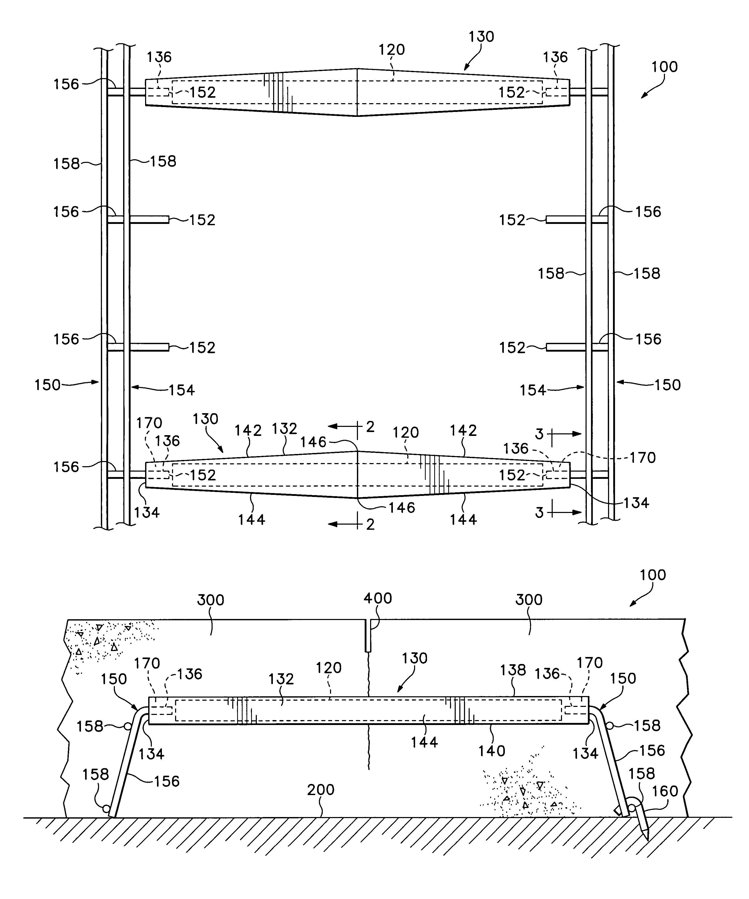
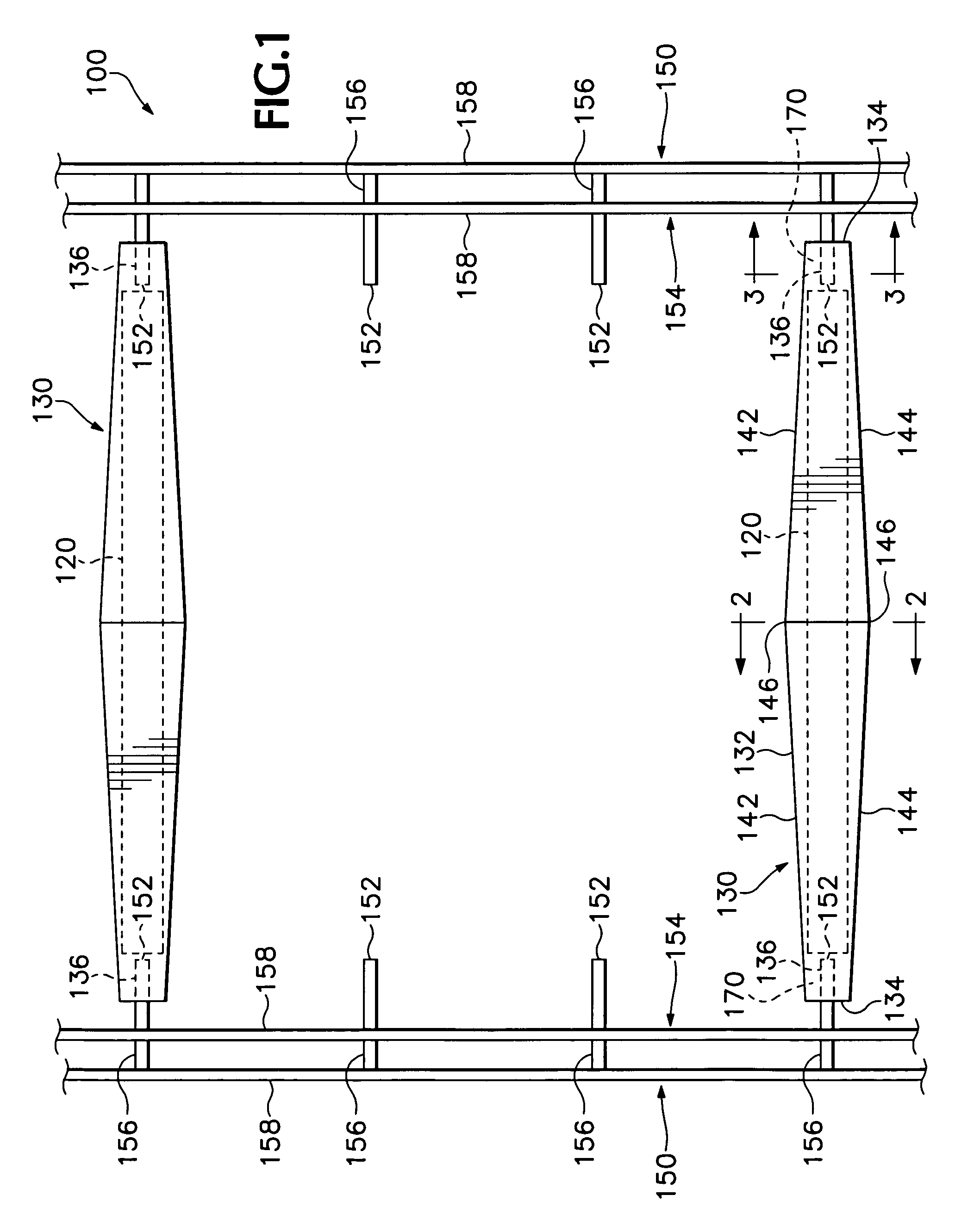
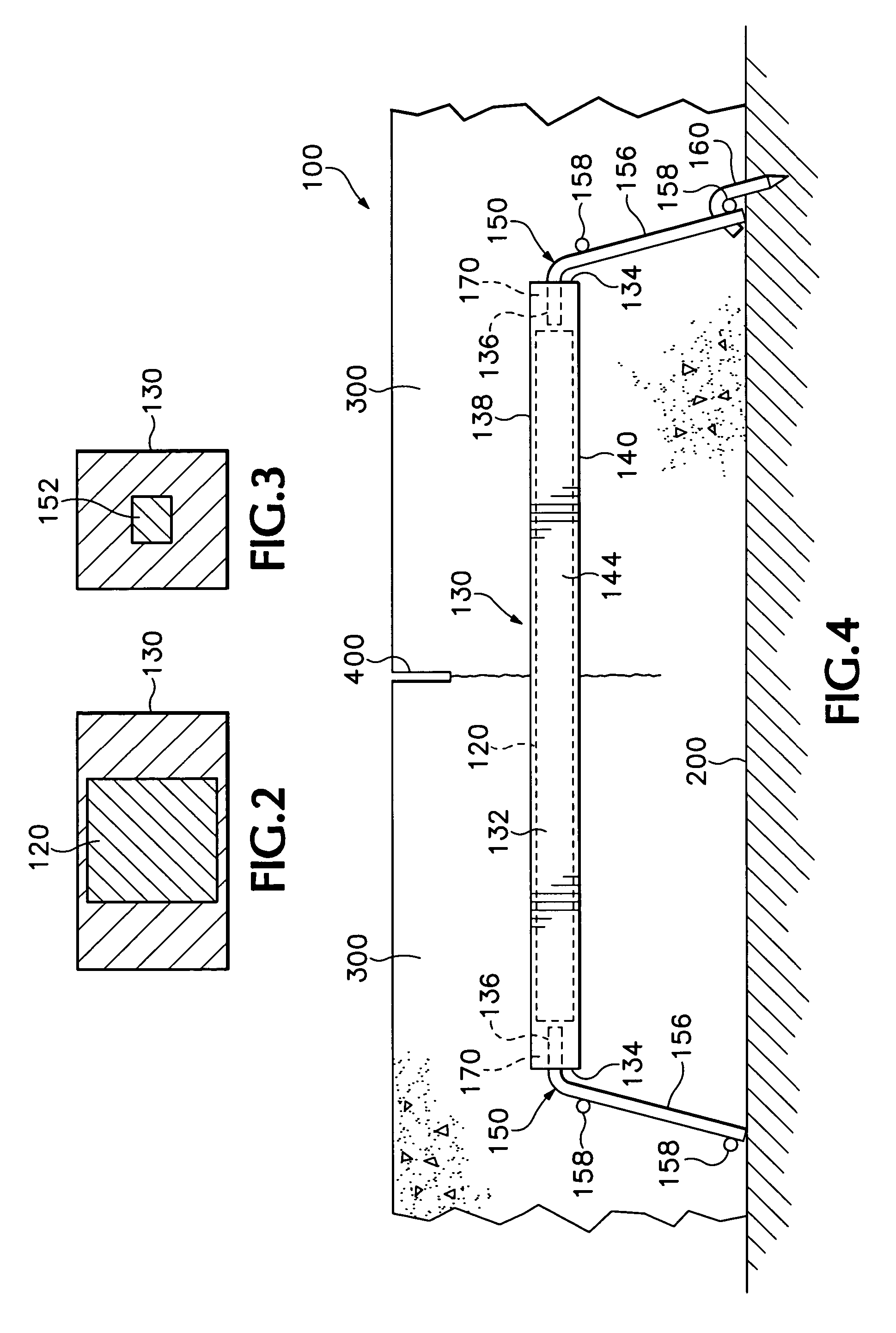
[0037]Conventional slab dowels are positioned within concrete sections. In a typical concrete formation sequence, the first concrete slabs and second concrete slabs are poured in sequence. Transverse joints are then saw cut or formed through methods well known in the prior art to reduce and / or relieve stresses in the concrete and prevent cracking. A longitudinal joint is formed between the two concrete strips comprising the first concrete slab and the second concrete slab.

[0038]Dowel bars are embedded in the concrete slabs for maintaining adjacent sections of concrete in alignment during contraction and expansion of the concrete, and for transferring shear stresses and bending moments across a joint formed between adjacent concrete slabs. The cross-sectional sizes and lengths of the dowel bars vary depending on the types of installation and the required forces to be counteracted. The dowel bars are placed and supported with respect to transverse joints and longitudinal joint.

[0039]A...


PUM


Abstract

A sleeve assembly system, a concrete dowel slab joint system, a method for maintaining adjacent sections of concrete in alignment during contraction and expansion of the concrete and for transferring shear stresses and bending moments across a joint formed between adjacent concrete slabs, and a concrete slab including a plurality of concrete dowel slab joint systems are provided. The concrete dowel slab joint system comprises the sleeve assembly for receiving and maintaining the dowel bar therewithin. The sleeve assembly is designed so that the dowel bar does not transmit substantial shear stresses to the concrete during the contraction and expansion of the concrete. A pair of bracket members, located on an underlying surface, support the sleeve assembly and the dowel bar above the underlying surface.

Description

BACKGROUND OF THE INVENTION[0001]This invention relates to dowel systems which can be employed as tying members between concrete bodies, and more particularly, to dowel systems which facilitate load transfer and dowel slippage across slab joints so as for maintaining the structural integrity of concrete slabs.[0002]Concrete responds to changes in temperature and moisture when movement associated with these changes (or for other reasons such as internal chemical reaction) is restrained. In these instances stresses develop that can lead to cracking. To control cracking, joints are built at interval distances short enough to maintain stresses in the concrete below certain critical values. Transverse joints are saw cut, placed through induced cracking, or formed at predetermined spacings.[0003]Concrete pavements for highways, airport runways and the like are generally placed in strips or lanes with a longitudinal joint formed between adjacent strips or lanes. Concrete is poured in the f...

Claims


Application Information

Patent Timeline
Patent Type & Authority Patents(United States)
IPC IPC(8): E01C11/18
CPCE01C11/14
Inventor KRAMER, DONALD R.
Owner KRAMER DONALD R
Learn More