Fuel supply system of internal combustion engine
a fuel supply system and internal combustion engine technology, applied in the direction of fuel injecting pumps, machines/engines, electric control, etc., can solve the problems of insufficient vehicle occupants suffering discomfort, and noise generated by operation (collision noise), so as to promote atomization of injected fuel, improve engine starting performance and exhaust emission, and improve fuel atomization
- Summary
- Abstract
- Description
- Claims
- Application Information
AI Technical Summary
Benefits of technology
Problems solved by technology
Method used
Image
Examples
first embodiment
[0030
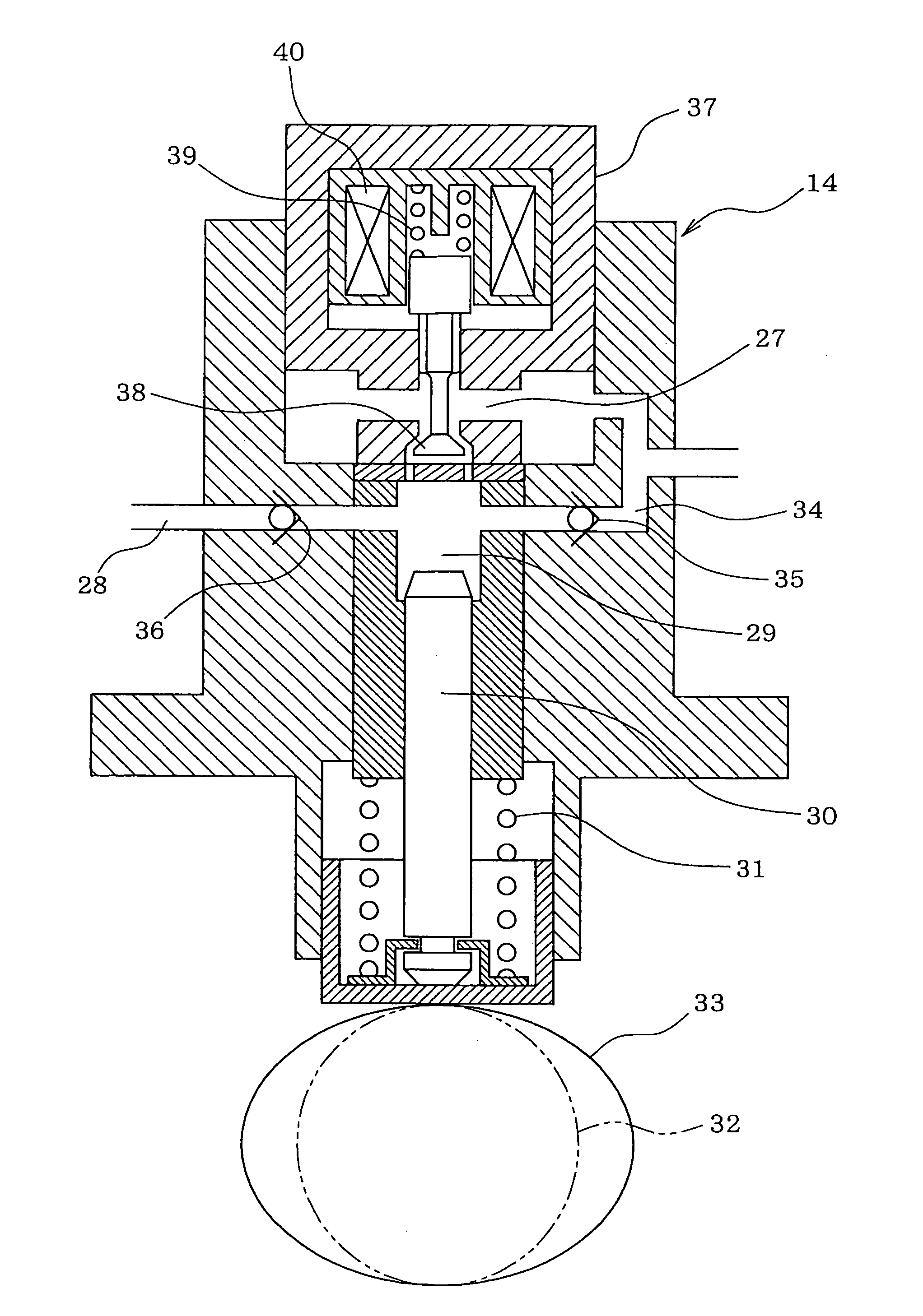
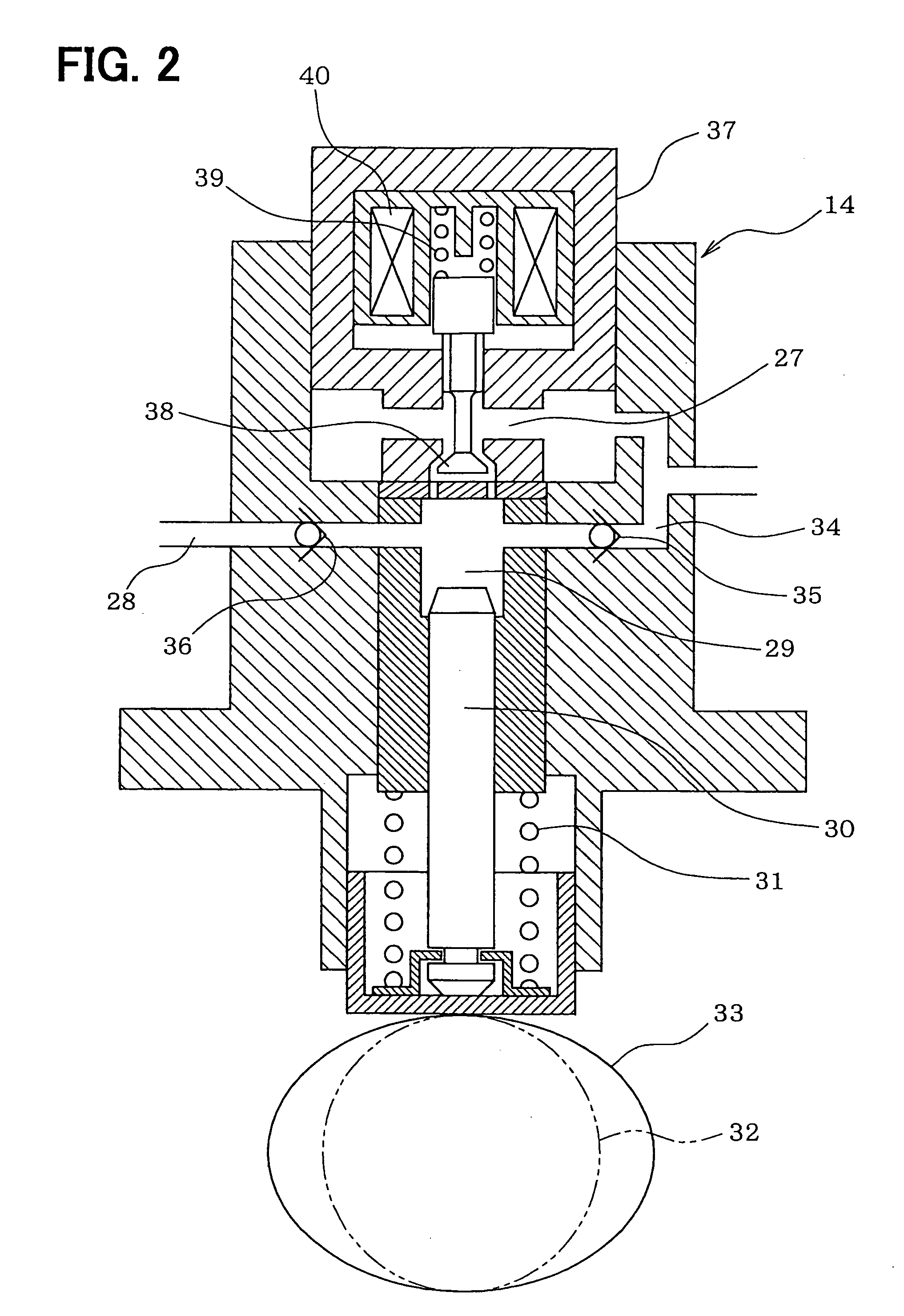
[0031]Referring to FIG. 1, a fuel supply system of a direct injection type gasoline engine (an internal combustion engine) according to a first embodiment of the present invention is illustrated. An electric low-pressure pump 12 for drawing fuel is disposed in a fuel tank 11 storing the fuel. The low-pressure pump 12 is driven by an electric motor using a battery as a power source. The fuel discharged from the low-pressure pump 12 is supplied to a mechanical high-pressure pump 14 through a low-pressure side fuel pipe 13. A fuel filter 15 is disposed in the low-pressure side fuel pipe 13. A low-pressure regulator 16 is connected to the low-pressure side fuel pipe 13. The low-pressure regulator 16 regulates a discharge pressure of the low-pressure pump 12 (a fuel supply pressure to the high-pressure pump 14) to a predetermined pressure. Excess fuel causing a pressure higher than the predetermined pressure is returned into the fuel tank 11 through a fuel return pipe 17.
[0032]The f...
second embodiment
[0049
[0050]Next, a fuel supply system according to a second embodiment of the present invention will be explained based on FIG. 6.
[0051]As explained above, the high-pressure pump 14 suctions the fuel through the secondary suction passage 34 during the valve closing control of the electromagnetic valve 37. However, the fuel injection quantity of the engine decreases when the engine is in a low rotation speed operation state (for instance, the idling operation state), in which the valve closing control is performed.
[0052]Therefore, in the second embodiment, a restriction passage portion 41, of which a passage sectional area is narrowed, is formed in the secondary suction passage 34 of the high-pressure pump 14 on an upstream side or a downstream side of the check valve 35 as shown in FIG. 6. The passage sectional area of the restriction passage portion 41 is larger than an area capable of suctioning the fuel quantity corresponding to the fuel injection quantity in the idling operation...
third embodiment
[0054
[0055]Next, a fuel supply system according to a third embodiment of the present invention will be explained based on FIG. 7.
[0056]As explained above, the ECU 26 recognizes the phase of the pump cam 33 (the phase of the plunger 30) based on the crank angle sensed by the crank angle sensor 24 and controls the energization of the electromagnetic valve 37 based on the crank angle. Thus, the ECU 26 controls the opening timing and the closing timing of the electromagnetic valve 37 with respect to the reciprocating movement of the plunger 30. Therefore, the crank angle (the phase of the pump cam 33) cannot be sensed before the crank angle determination (the cylinder determination) based on the output signal of the crank angle sensor 24 and the like is completed during the engine starting period. At that time, the ECU 26 cannot control the opening timing and the closing timing of the electromagnetic valve 37 with respect to the reciprocating movement of the plunger 30.
[0057]Therefore, ...
PUM
 Abstract
Description
Claims
Application Information
 - R&D
- Intellectual Property
- Life Sciences
- Materials
- Tech Scout
- Unparalleled Data Quality
- Higher Quality Content
- 60% Fewer Hallucinations
Browse by: Latest US Patents, China's latest patents, Technical Efficacy Thesaurus, Application Domain, Technology Topic, Popular Technical Reports.
© 2025 PatSnap. All rights reserved.Legal|Privacy policy|Modern Slavery Act Transparency Statement|Sitemap|About US| Contact US: help@patsnap.com


