
Method of making inlaid color filter arrays

a filter array and color technology, applied in the field of color filter arrays, can solve the problems of limiting the smallest dimension which can be used over very small filter elements, loss of edge sharpness of filter elements, and swelling of the receiving layer, so as to achieve high quality uniformity over large areas, precise control of layer thickness, and effective utilization of evaporant materials

Active Publication Date: 2007-03-27
OMNIVISION TECH INC
View PDF50 Cites 38 Cited by
  • Summary
  • Abstract
  • Description
  • Claims
  • Application Information

AI Technical Summary

Problems solved by technology

An additional problem associated with this process is that the dye receiving layers swell upon the introduction of dyes, often overlapping one another and also limiting the smallest dimension which can be attainable for use over very small filter elements.
In addition, the dyes spread within the dye receiving layer, resulting in loss in edge sharpness of the filter elements.
Another problem with this process is that dyes are susceptible to fading on exposure to light.
One problem encountered in both the use of dispersions and in the use of dyed polymers for making color filter arrays is the difficulty in aligning the different color filter layers for each color, so that they do not overlap in regions where overlaps are not desired.
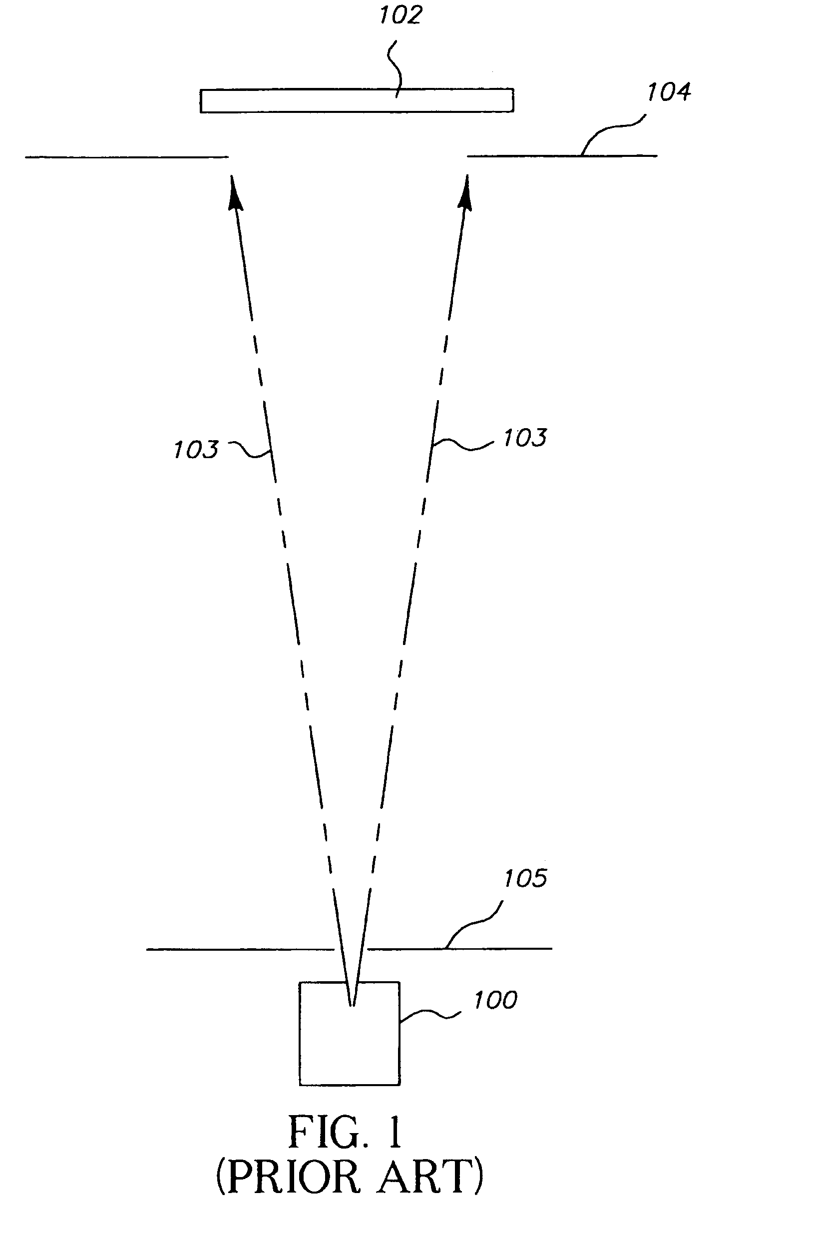
There are a number of problems associated with this technique which involves depositing layers in a partial vacuum and is frequently referred to in the art as physical vapor deposition (PVD).
In certain cases, it is difficult to control the thickness and uniformity of the colorant deposited on the substrate.
However, the colorant material may deposit on the mask and vacuum fixtures to such a degree that it flakes off, creating undesirable contamination and waste of the colorant and requiring frequent clean-up.
In addition, the moving fixtures may generate undesirable particulate materials which may cause contamination of the substrate.
Some other shortcomings in making color filter arrays by the PVD process are the need to use a large source-to-substrate spacing which requires large chambers and large pumps to reach a sufficient vacuum, and the need for masks which cause low-material utilization and build-up on the mask with the concomitant contamination problems.
Very specific off-axis source location relative to the substrate, which is sometimes needed for uniform coating, causes very poor material utilization.
Still further, source replenishment problems exist for coating multiple substrates in one pump-down.
Because of this, the alignment of successive patterns is often difficult, and overlaps between colors consequently hard to control.

Method used


Image

  • Method of making inlaid color filter arrays
  • Method of making inlaid color filter arrays
  • Method of making inlaid color filter arrays

Examples


example 1

[0035]A tantalum boat was half-filled with about 0.1 gm of Pigment Yellow 110 (Ciba-Geigy Corp.), placed under a partial vacuum of about 2.5×10E−5 Torr, and heated to a temperature of 375–417 degrees C. by passing an electric current through it. The material which evaporated from the boat was condensed on a section of stainless steel foil, about 25 microns thick, maintained at ambient temperature. The thickness of the deposit was monitored by an oscillating quartz crystal monitor, and was stopped when the thickness reached about 0.45 microns.

[0036]In a similar fashion, the coated steel foil was coated with about 0.15 microns of titanyl phthalocyanine (H.W. Sands Co.), at a pressure of about 2×10E−4 Torr and over a temperature range of 331–437 degrees C.

[0037]The double-coated steel foil was positioned about 2 mm from a glass slide, clamped between two electrodes, placed in a partial vacuum of about 3.3×10E−5 Torr, and heated by the passage of an electric current at 30 volts for 10 s...

example 2

[0038]A similar procedure was followed as given in Example 1, except that the colorants were deposited in the reverse order. The colorants transferred completely to the glass slide, and appeared to form a clear, continuous layer.

example 3

[0039]Commercially obtained titanyl phthalocyanine (Aldrich Chemical Co.) was placed in a tantalum boat and heated by passing electrical current through it, while maintaining a reduced pressure of about 1.1×10E−4 Torr in a vacuum bell jar. About 0.15 microns of the phthalocyanine were deposited onto a section of stainless steel foil, having a thickness of about 25 microns. The coated foil was used as the substrate for a second colorant layer in a second step, heating Pigment Orange 36 (Novoperm Orange HL-70 from Hoechst Celanese Corp.) in a tantalum boat at a pressure of about 1.3×10E−4 Torr. About 0.3 microns of the pigment were deposited on the phthalocyanine coating, forming a double-layer coating on the steel foil. The double-coated foil was then mounted about 2 mm distant from a section of a silicon wafer bearing an adhesion promoting layer of 1.0 microns of poly(methyl glutarimide) (PMGI from Microelectronics Chemical Corp.) and a patterned layer of AZ5214IR photoresist (Hoech...


PUM

PropertyMeasurementUnit
pressuresaaaaaaaaaa
distanceaaaaaaaaaa
pressureaaaaaaaaaa

Abstract

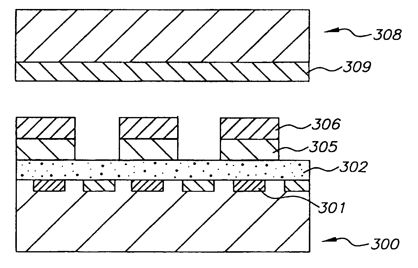
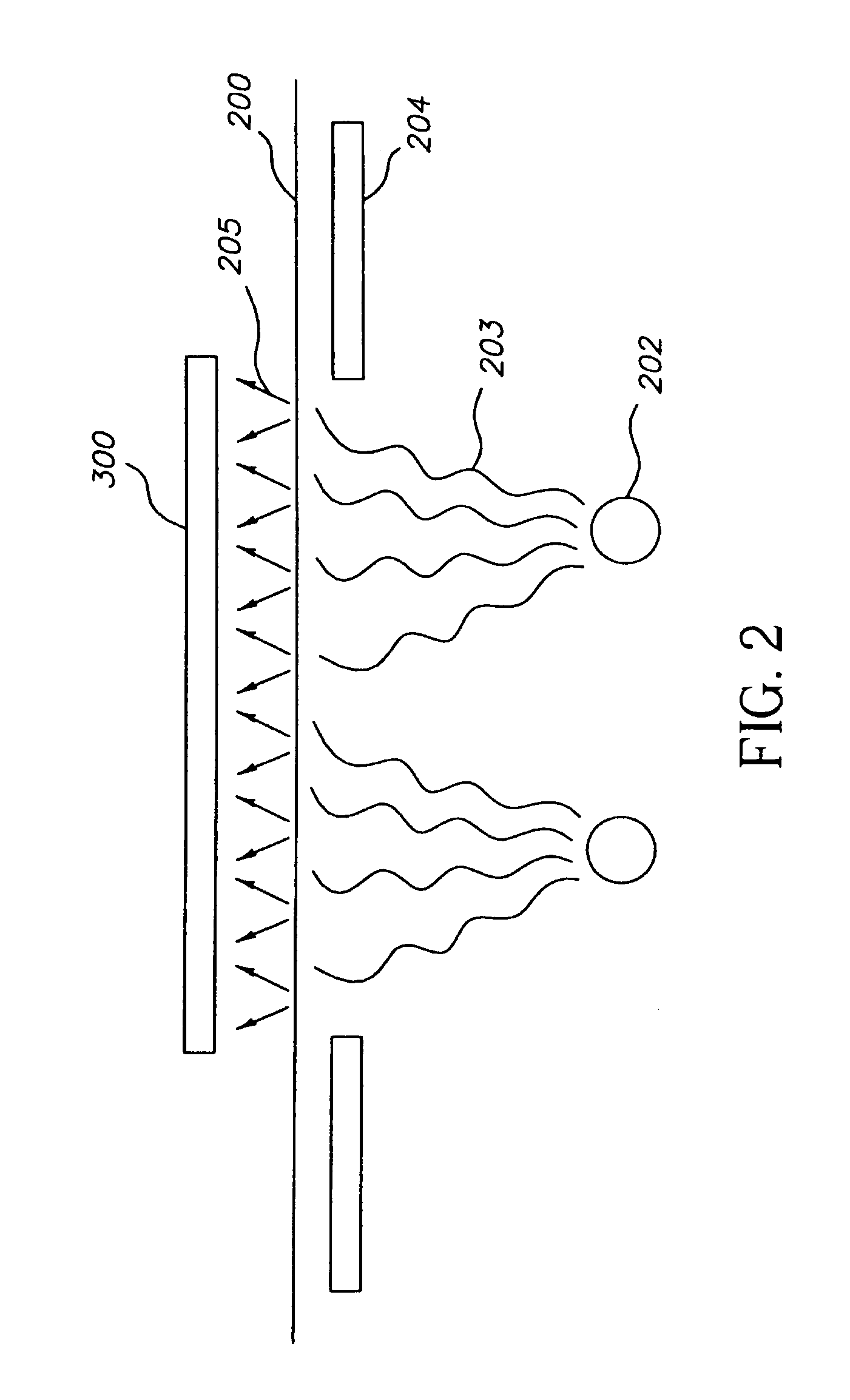
A method of making a color filter array on a first substrate comprising the steps of: providing at least one transferable colorant layer on a second substrate and positioning such transferable layers in transferable relationship with but spaced a distance from the first substrate; and heating the second substrate sufficiently to simultaneously transfer the colorant materials from the heat transferable colorant layers to the first substrate. An etch process is used to form openings in the first colorant, into which subsequent colorants are deposited.

Description

CROSS REFERENCE TO RELATED APPLICATIONS[0001]The present invention is related to U.S. Pat. No. 5,688,551, issued on Nov. 18, 2997 and entitled “Method of Forming an Organic Electroluminescent Display Panel,” by Littman, et al.FIELD OF THE INVENTION[0002]The present invention relates to a method of making color filter arrays which are suitable for display applications such as liquid crystal displays or light emitting diode displays and are particularly suitable for use on image sensors, either as an integral part of the sensor or as an optical element that is used in conjunction with the sensor.BACKGROUND OF THE INVENTION[0003]In making color filter arrays, separate layers of different colors must be formed. Frequently these layers are formed using dye as the colorant material which is imbibed into dye receiving layers which must be of a controlled thickness, and a precise amount of dye must be used to achieve the appropriate color. See, for example, commonly assigned U.S. Pat. No. 4...

Claims


Application Information

Patent Timeline
Patent Type & Authority Patents(United States)
IPC IPC(8): G02B5/20
CPCG02B5/201
Inventor ROBERTS, LUTHER C.
Owner OMNIVISION TECH INC
Learn More