
Sand control screen assembly having fluid loss control capability and method for use of same

a technology of fluid loss control and screen assembly, which is applied in the direction of drinking water installation, wellbore/well accessories, construction, etc., can solve the problems of abrasive wear of components within the well, need for an expensive workover, and many problems

Inactive Publication Date: 2007-03-20
HALLIBURTON ENERGY SERVICES INC
View PDF131 Cites 74 Cited by
  • Summary
  • Abstract
  • Description
  • Claims
  • Application Information

AI Technical Summary

Benefits of technology

The present invention provides a sand control screen assembly and a treatment method for use in wellbores that can prevent fluid loss and allow for the production of fluids from the formations. The assembly includes a base pipe with an opening and a filter medium that allows fluid to flow through while preventing particulate flow. An isolation member is positioned inside the base pipe to form an annular region and a one-way valve is positioned within the annular region to control fluid flow. The assembly can be used in a downhole treatment method where a treatment fluid is pumped into the production interval and allowed to return through the sand control screen assembly. The technical effects of the invention include preventing fluid loss, allowing for the production of fluids from the formations, and facilitating the treatment of wellbores.

Problems solved by technology

Numerous problems may occur as a result of the production of such particulate.
For example, the particulate causes abrasive wear to components within the well, such as tubing, pumps and valves.
In addition, the particulate may partially or fully clog the well creating the need for an expensive workover.
It has been found, however, that following formation treatment operations, the fluid inside the sand control screen tends to leak off into the adjacent formation.
This leak off not only results in the loss of the relatively expensive fluid into the formation, but may also result in damage to the gravel pack around the sand control screen and damage to the formation.
This fluid leak off is particularly problematic in cases where multiple production intervals within a single wellbore require treatment, as the fluid remains in communication with the various formations for an extended period of time.

Method used


Image

  • Sand control screen assembly having fluid loss control capability and method for use of same
  • Sand control screen assembly having fluid loss control capability and method for use of same
  • Sand control screen assembly having fluid loss control capability and method for use of same

Examples


Embodiment Construction

[0030]While the making and using of various embodiments of the present invention are discussed in detail below, it should be appreciated that the present invention provides many applicable inventive concepts which can be embodied in a wide variety of specific contexts. The specific embodiments discussed herein are merely illustrative of specific ways to make and use the invention, and do not delimit the scope of the present invention.

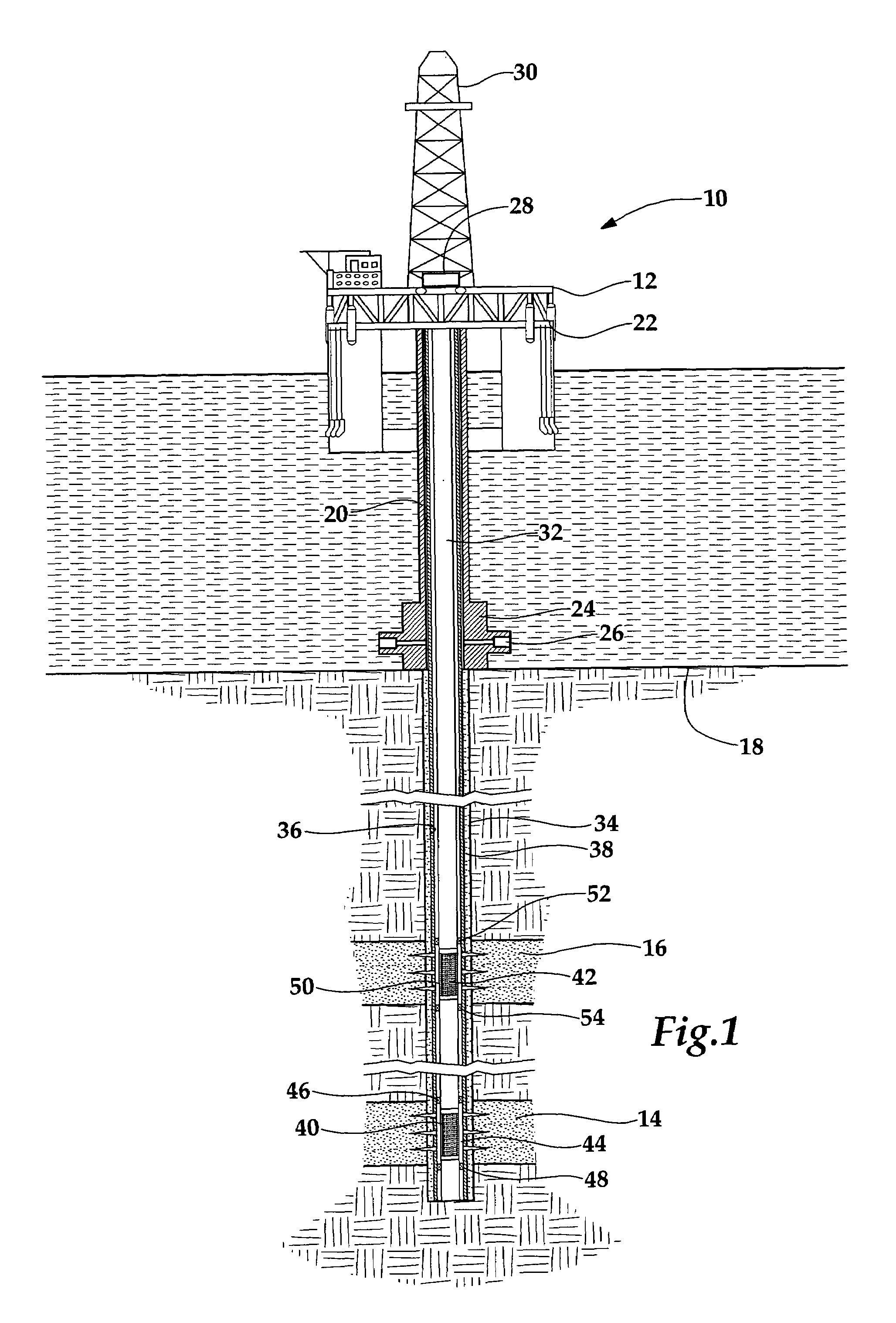
[0031]Referring initially to FIG. 1, a pair of sand control screen assemblies used during the treatment of multiple intervals of a wellbore and operating from an offshore oil and gas platform is schematically illustrated and generally designated 10. A semi-submersible platform 12 is centered over a pair of submerged oil and gas formations 14, 16 located below a sea floor 18. A subsea conduit 20 extends from a deck 22 of the platform 12 to a wellhead installation 24 including blowout preventers 26. Platform 12 has a hoisting apparatus 28 and a derrick 30...


PUM


Abstract

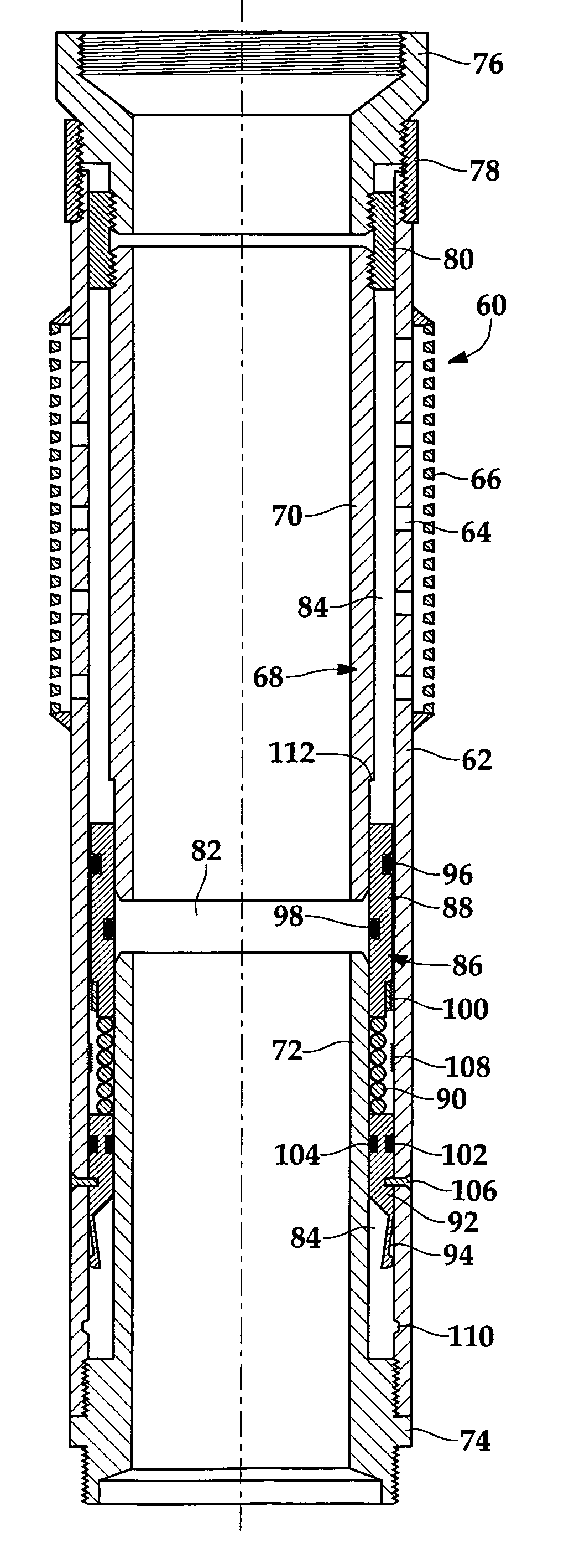
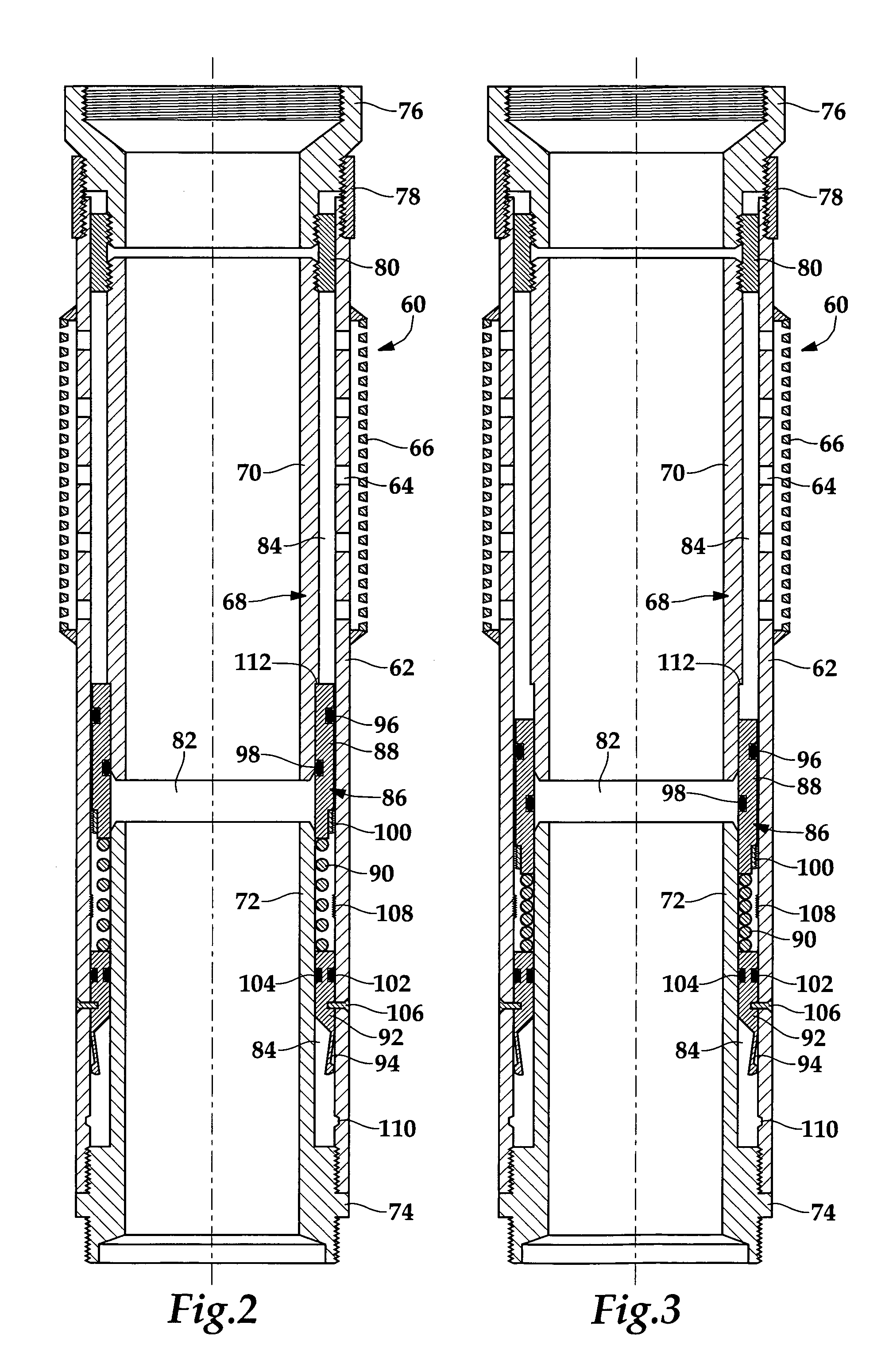
A sand control screen assembly (60) that is positionable within a wellbore includes a base pipe (62) having at least one opening (64) that allows fluid flow therethrough and a filter medium (66) positioned exteriorly of the base pipe (62) that selectively allows fluid flow therethrough and prevents particulate flow of a predetermined size therethrough. An isolation member (68) is positioned interiorly of the base pipe (62) forming an annulus (84) therewith. A one-way valve (86) is slidably operable within the annulus (84). The one-way valve (86) controls the flow of fluid through sand control screen assembly (60) such that fluid flow is selectively prevented from the interior to the exterior of the sand control screen assembly (60) but is allowed from the exterior to the interior of the sand control screen assembly (60).

Description

TECHNICAL FIELD OF THE INVENTION[0001]This invention relates, in general, to a sand control screen assembly positioned in a production interval of a wellbore and, in particular, to a sand control screen assembly having fluid loss control capability that selectively prevents fluid flow from the interior to the exterior of the sand control screen assembly.BACKGROUND OF THE INVENTION[0002]It is well known in the subterranean well drilling and completion art that relatively fine particulate materials may be produced during the production of hydrocarbons from a well that traverses an unconsolidated or loosely consolidated formation. Numerous problems may occur as a result of the production of such particulate. For example, the particulate causes abrasive wear to components within the well, such as tubing, pumps and valves. In addition, the particulate may partially or fully clog the well creating the need for an expensive workover. Also, if the particulate matter is produced to the surfa...

Claims


Application Information

Patent Timeline
Patent Type & Authority Patents(United States)
IPC IPC(8): E21B43/08
CPCE21B34/063E21B43/088E21B43/08E21B43/045
Inventor RICHARDS, WILLIAM MARK
Owner HALLIBURTON ENERGY SERVICES INC
Learn More