
Medicament dispenser

a technology of medicine dispensers and dispensers, applied in the field of medicine dispensers, can solve the problems of counterfeiting, widespread use, and use of out-of-date or counterfeit cartridge reloads, and achieve the effect of facilitating detection and prevention of counterfeiting, and being easy to transfer and accurately transfer

Inactive Publication Date: 2007-03-20
GLAXO GROUP LTD
View PDF146 Cites 121 Cited by
  • Summary
  • Abstract
  • Description
  • Claims
  • Application Information

AI Technical Summary

Benefits of technology

[0017]One advantage of the present invention is the ability to store many types of information in different parts of the memory structure of the transceivers. The information is furthermore stored in a form which is readily and accurately transferable.
[0031]The memory will typically comprise an integrated circuit chip. Either transceiver may be configured to have a memory structure which allows for large amounts of information to be stored thereon. The memory structure can be arranged such that parts of the memory are read-only, being programmed during / after manufacture, other parts are read / write and further parts are password protectable. Initial transfer of information (e.g. on manufacture or one dispensing) to or from any transceiver can be arranged to be readily achievable by the use of a reader which is remote from the medical dispenser, thereby minimising the need for direct product handling. In further aspects, the reader can be arranged to simultaneously read or write to the memory of multiple transceivers on multiple medicament dispensers.
[0047]In another aspect, the tag is located within the medicament container, for example, as a loose component together with any medicament contents thereof or within a separate compartment or housing within the medicament container. An advantage of placing the tag within the medicament container is that is can be ‘hidden from view’ thereby improving its utility as a security feature. Additionally, the tag and container may be configured (e.g. shaped and sized) such that the tag may only be removed by rupture or other degradation of the medicament container or tag.
[0072]Suitably, the medicament dispenser additionally comprises a safety mechanism to prevent unintended multiple actuations of the release means. The patient is thereby protected from inadvertently receiving multiple doses of medicament in a situation where they take a number of short rapid breaths. More preferably, the safety mechanism imposes a time delay between successive actuations of the release means. The time delay is typically of the order of from three to thirty seconds.
[0080]In a further aspect, the communicator communicates with the gateway via a second communications device. Preferably, the second communications device is a telecommunications device, more preferably a cellular phone or pager. Preferably, the communicator communicates with the second communications device using spread spectrum radiofrequency signals. A suitable spread spectrum protocol is the Bluetooth (trade mark) standard which employs rapid (e.g. 1600 times a second) hopping between plural frequencies (e.g. 79 different frequencies). The protocol may further employ multiple sending of data bits (e.g. sending in triplicate) to reduce the effects of external interference.

Problems solved by technology

Counterfeiting is known to be a problem with medical dispensers given the often-high resale value of the product.
There are a number of potential challenges associated with reloadable medicament dispensers and these have hitherto prevented their widespread use.
A primary challenge is to ensure that the reload is employed with the correct actuator housing.
Secondary challenges include preventing the use of out-of-date or counterfeit cartridge reloads.
Tailoring the actuator housing to be only operable (e.g. mechanically operable) with the correct reload is a feasible, but expensive and therefore commercially unattractive solution to the primary challenge.
If product integrity problems are detected the dispenser may automatically shutdown.
Furthermore, contact between the strips on the container and the electrical contact fingers is required which requires physical tailoring of the container to the housing, thereby limiting product design options.

Method used


Image

  • Medicament dispenser
  • Medicament dispenser
  • Medicament dispenser

Examples


Embodiment Construction

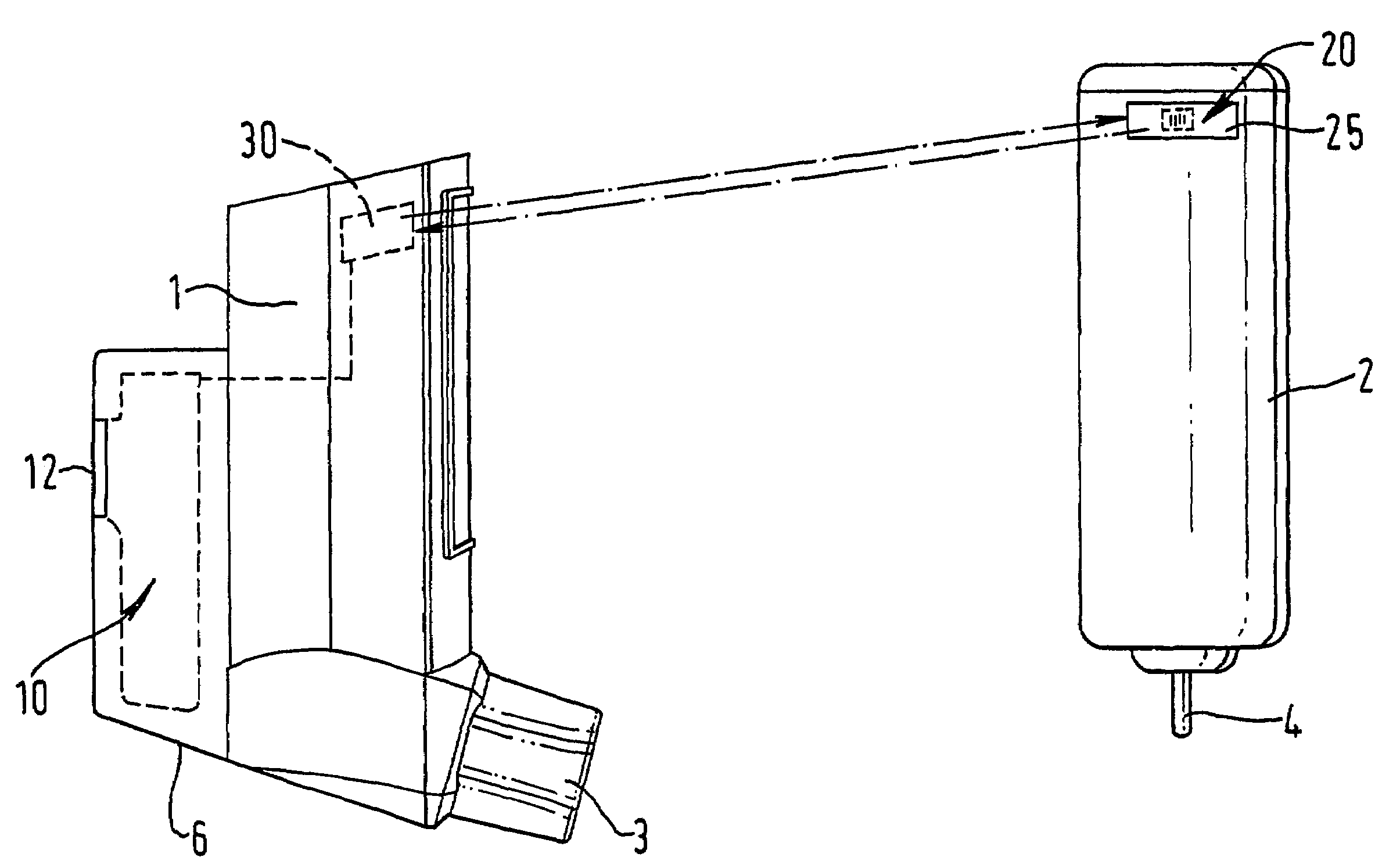
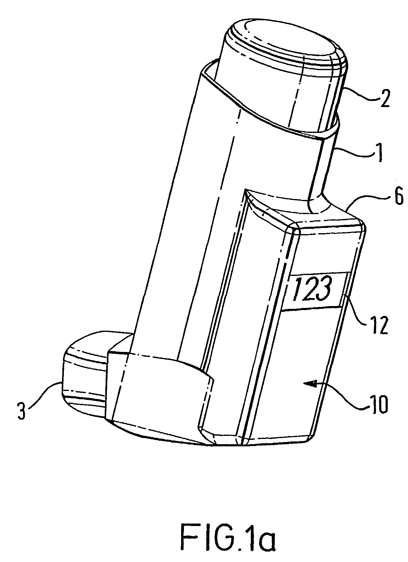
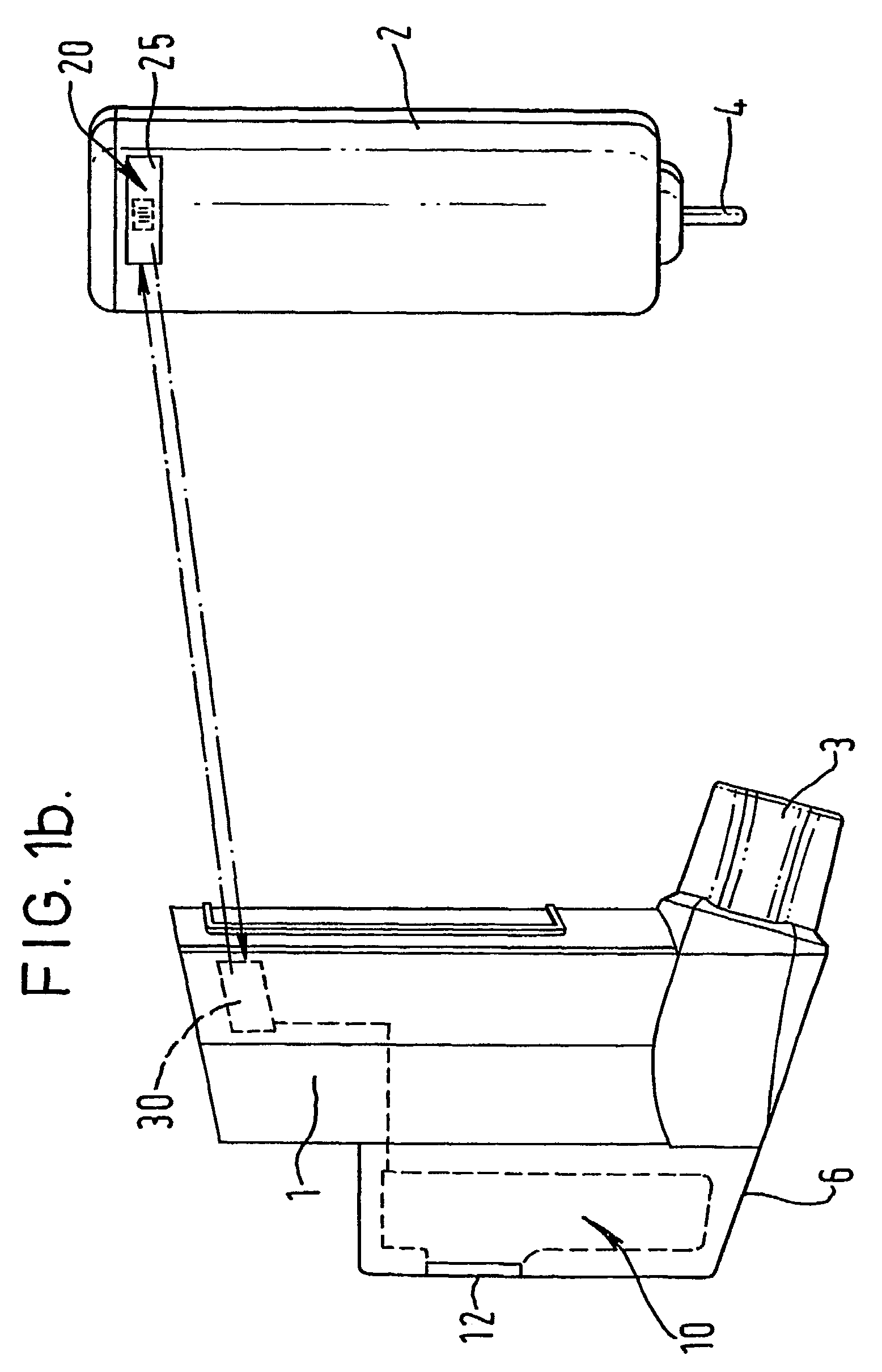
[0129]FIGS. 1a and 1b show a metered dose inhaler comprising a tubular actuator housing 1 shaped for receipt of an aerosol container 2. The actuator housing is open at one end and is closed at the other. An outlet 3 leads laterally from the closed end of the housing 1. In the embodiment illustrated, the outlet 3 is in the form of a mouthpiece intended for insertion into the mouth of the patient but it may, if desired, be designed as a nozzle for insertion into the patient's nostril. The aerosol container 2 has an outlet valve 4 at one end. This valve acts as a release means for release of a measured dose from the aerosol container. The release means is actuable by inward movement of the valve 4 relative to the aerosol container 2.

[0130]The metered dose inhaler of FIGS. 1a and 1b includes an electronic data management system 10 comprised within an extended part of the housing 6. Visual display monitor 12 allows for display of information from the electronic data management system 10 ...


PUM


Abstract

A medicament dispenser for use in the storage, presentation and / or dispensing of medicament comprising a body shaped for receipt of a medicament container. In association with the body, there is a first transceiver for transmitting and receiving data. A medicament container is receivable by the body. In association with the medicament container, there is a second transceiver for transmitting and receiving data. Data is transferable in two-way fashion from the first transceiver to the second transceiver. The medicament dispenser may be supplied in kit of parts form.

Description

CROSS-REFERENCE TO RELATED APPLICATIONS[0001]This application is filed pursuant to 35 USC 371 as a United States National Phase Application of International Patent Application Serial No. PCT / EP01 / 07968 filed 11 Jul. 2001, which claims priority from GB0017301.3 filed on 15 Jul. 2000 in the United Kingdom, and GB0020538.5 filed on 22 Aug. 2000 in the United Kingdom.FIELD OF THE INVENTION[0002]The present invention relates to a medicament dispenser for use in the dispensing of medicament. The medicament dispenser has a medicament container (e.g. in the form of a reloadable cartridge).BACKGROUND OF THE INVENTION[0003]Medical dispensers are well known for the dispensing of various kinds of medicament. Inhalation devices, such as metered dose inhalers (MDI) and dry powder inhalers are known for the delivery of medicament for the treatment of respiratory disorders. Syringes, including needleless syringes are also known for the delivery of injectable medicament to a patient.[0004]The manufa...

Claims


Application Information

Patent Timeline
IPC IPC(8): A61M11/00A61M15/00A62B9/00A61J1/14A61J7/04A61M13/00A61M16/00A61M16/16G06K17/00G06K19/00H04B1/59
CPCA61M16/161A61M15/009A61M15/0051A61M15/0068A61M15/008A61M15/0065A61J2007/0418A61M2016/0027A61M2016/0036A61M2205/3306A61M2205/3368A61M2205/3553A61M2205/3584A61M2205/52A61M2205/60A61M2205/6018A61M2205/6054A61M2205/80A61M2205/8206A61M2209/06A61M2230/42A61M2230/43A61M2230/432A61M2230/435A61M2230/63A61J7/0418A61M16/026
Inventor BRAND, PETER JOHNGODFREY, JAMES WILLIAMRAND, PAUL KENNETH
Owner GLAXO GROUP LTD
Learn More