
Micro-electromechanical switch performance enhancement

a micro-electromechanical and switch technology, applied in the field of micro-electromechanical switches, to achieve the effect of improving the reliability, improving the actuation speed of the switch, and enhancing the switch performan

Inactive Publication Date: 2007-03-13
TERAVICTA TECH
View PDF18 Cites 12 Cited by
  • Summary
  • Abstract
  • Description
  • Claims
  • Application Information

AI Technical Summary

Benefits of technology

This approach effectively maintains and improves the performance of micro-electromechanical switches by reducing resistance, preventing sticking, and enhancing switching speed and reliability through contact conditioning and tailored voltage profiles.

Problems solved by technology

However, if the contact area is more deteriorated, then conditioning may include reforming or replenishing the contact area back to its original performance level.

Method used


Image

  • Micro-electromechanical switch performance enhancement
  • Micro-electromechanical switch performance enhancement
  • Micro-electromechanical switch performance enhancement

Examples


Embodiment Construction

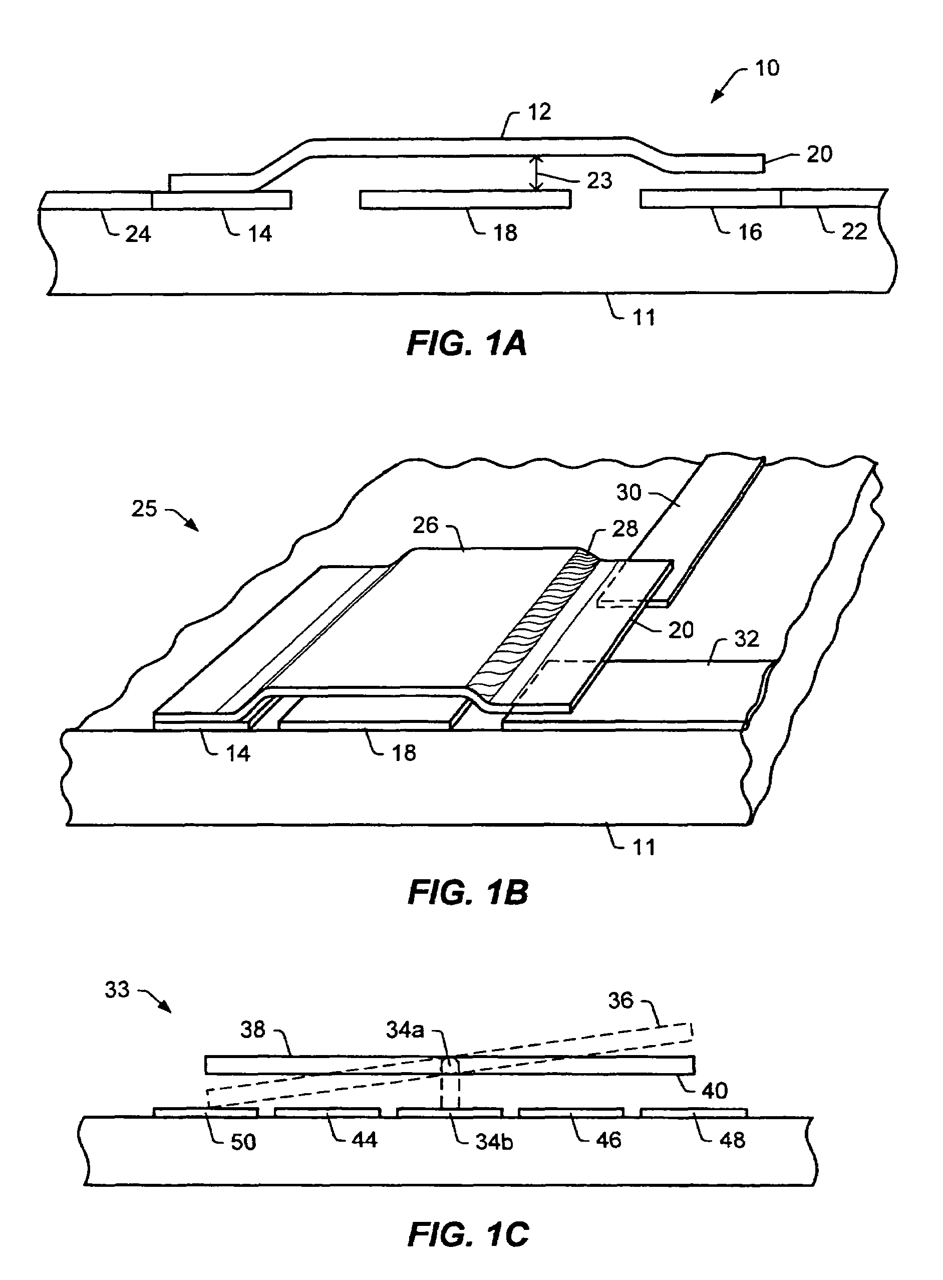
[0033]A cross-sectional view of a MEMS cantilever switch 10 is shown in FIG. 1A. Conductive beam 12 is fixed at one end to contact pad 14. The other end of beam 12 resides a spaced distance above a second contact pad 16 when the switch is open, as in FIG. 1. Gate electrode, or control element, 18 underlies beam 12 between the two contact pads. In the electrostatic switch of FIG. 1, application of an electrostatic potential difference between gate electrode 18 and beam 12 creates an attractive electrostatic force between them, causing beam 12 to move downward. Contact element 20 at the end of beam 12 is thereby connected to contact pad 16, so that a signal may be passed between contact pads 14 and 16 along beam 12. The switch remains closed as long as the potential is applied. Upon removing the applied potential, the spring force of the cantilever beam 12 should pull the beam back up, opening the switch. It is noted that in FIGS. 1A, 1B and 1C, as well as in the other perspective and...


PUM


Abstract

In methods and circuits for using associated circuitry to enhance performance of a micro-electromechanical switch, one of the method embodiments is a contact conditioning process including applying a time-varying voltage to the control element of a closed switch. In another embodiment, a voltage profile applied to the control element of the switch can be tailored to improve the actuation speed or reliability of the switch. In another method embodiment, the performance of a switch may be evaluated by measuring a performance parameter, and corrective action initiated if the switch performance is determined to need improvement. An embodiment of a circuit for maintaining performance of a micro-electromechanical switch includes first and second signal line nodes, sensing circuitry coupled to the signal line nodes and adapted to sense a performance parameter value of the switch, and control circuitry operably coupled to at least one terminal of the switch.

Description

PRIOR APPLICATION[0001]This application is a divisional application from prior application Ser. No. 10 / 229,586 filed Aug. 28, 2002.BACKGROUND OF THE INVENTION[0002]1. Field of the Invention[0003]This invention pertains to micro-electromechanical switches, and more particularly to the use of control circuitry to enhance performance and reliability of a switch.[0004]2. Description of the Related Art[0005]The following descriptions and examples are not admitted to be prior art by virtue of their inclusion within this section.[0006]Micro-electromechanical switches, or switches made using micro-electro-mechanical systems (MEMS) technology, are of interest in part because of their potential for allowing integration of high-quality switches with circuits formed using integrated circuit (IC) technology. As compared to transistor switches formed with conventional IC technology, for example, MEMS contact switches may exhibit lower losses and a higher ratio of off-impedance to on-impedance. (“...

Claims


Application Information

Patent Timeline
Patent Type & Authority Patents(United States)
IPC IPC(8): G06F13/40B81B3/00B81B7/02H01H1/00H01H1/60H01H9/00H01H11/00H01H47/00H01H47/04H01H49/00H01H59/00
CPCH01H1/0015H01H1/60H01H1/605H01H47/04H01H59/0009H01H11/0062H01H2059/0063H01H59/00
Inventor IVANCIW, DAN A.HILBERT, CLAUDE
Owner TERAVICTA TECH
Learn More