Digital automatic gain control for transceiver devices

a transceiver device and digital technology, applied in the field of wireless communication system methods and apparatus, can solve the problems of restricting the degree of integration with which a corresponding transceiver device may be manufactured, affecting the design complexity of the super-heterodyne architecture, and affecting the degree of integration. achieve the effect of effective gain control and adding to design complexity

Active Publication Date: 2007-02-27
MEDIATEK INC
View PDF9 Cites 15 Cited by
  • Summary
  • Abstract
  • Description
  • Claims
  • Application Information

AI Technical Summary

Benefits of technology

[0009]Generally, the present invention provides devices and methods for digitally controlling the gain of IF signals within a large dynamic range, wherein the settling time of the variable gain amplifiers is small, so that, in particular, the settling may be completed within the preamble of a data packet to match the receiver and the transmitter substantially without data loss. The present invention allows an effective gain control within a few clock cycles by employing a minimum number of digital components, such as an adder and a latch so that the automatic gain control may easily be integrated in a single chip transceiver for direct conversion without unduly adding to design complexity.

Problems solved by technology

A key issue in this respect is the degree of integration with which a corresponding transceiver device may be manufactured.
While for many applications, such as direct broadcast satellite (DBS) receivers and WLAN devices, this is of great importance due to cost effectiveness, in other applications such as mobile phones, mobile radio receivers and the like, low power consumption is of primary concern.
Although the super-heterodyne architecture is well established and allows the fabrication of reliably operating receiver devices, the highly selective IF filters that are necessary for the proper operation of these devices, require the employment of capacitors and inductors of high quality, thereby restricting the degree of integration achievable with a super-heterodyne architecture, since high quality inductors may not easily be implemented into a semiconductor substrate.
Moreover, the amplifiers operating at the relatively high IF require relatively large drive currents to provide for the required gain factor so that the power consumption of these devices may not be reduced to the levels of amplifiers operating at relatively low frequencies.
Despite these advantages, direct conversion devices exhibit a serious draw back in that any offset drift, for example caused by a slight miss match of the local oscillator with respect to the incoming RF signal, may not easily be separated and is thus a part of the baseband signal.
Since the QPSK signal does not have a constant envelope the received signal strength indicator level is difficult to estimate accurately.
Consequently, a relatively long settling time for a moderate dynamic range of the variable gain amplifier is required.

Method used


Image

  • Digital automatic gain control for transceiver devices
  • Digital automatic gain control for transceiver devices
  • Digital automatic gain control for transceiver devices

Examples


Embodiment Construction

[0020]It is to be noted that although the present invention is described with reference to the embodiments as illustrated in the following detailed description and in the accompanying drawings, the detailed description, as well as the drawings, are not intended to limit the present invention to the particular embodiment disclosed therein, but rather, the described embodiments merely exemplify the various aspects of the present invention, the scope of which is defined by the appended claims.

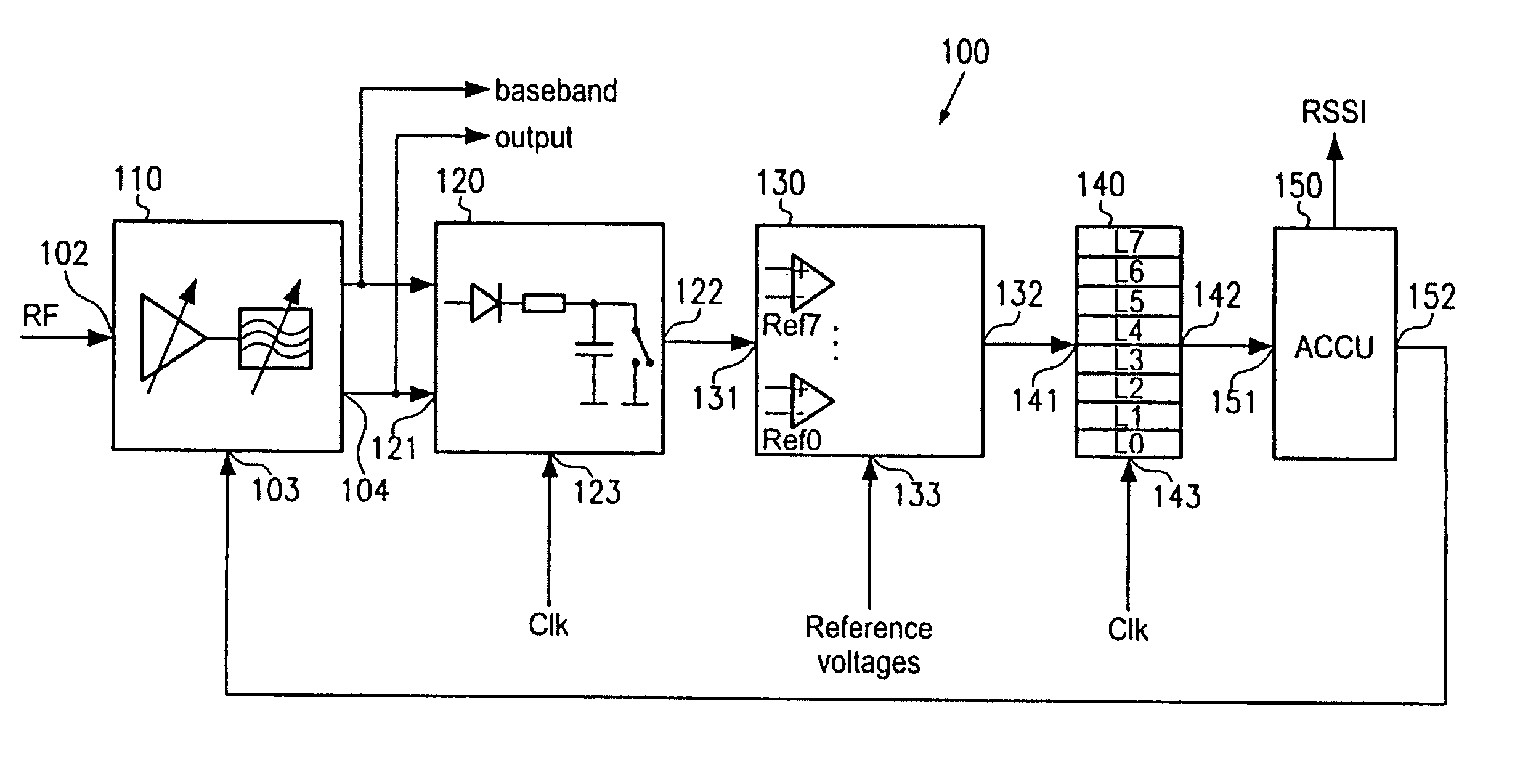
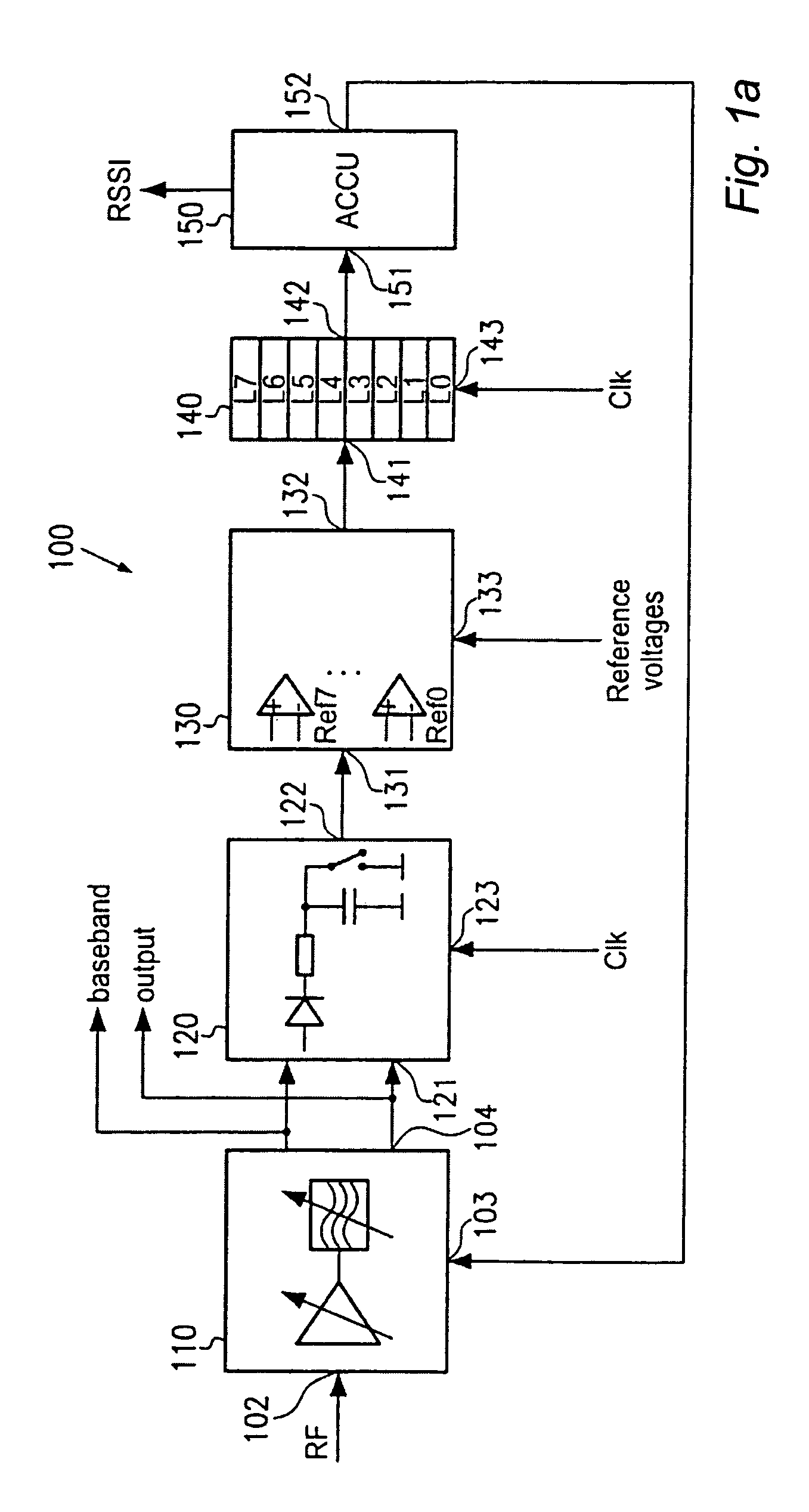
[0021]With reference to FIG. 1a, one illustrative embodiment will now be described. A transceiver device 100 comprises a variable gain amplifier and filter section 110, henceforth referred to variable gain section, having an input 102 for receiving an RF signal, an input 103 for receiving a gain setting signal and an output 104 for supplying an IF signal, such as a baseband signal when a direct conversion architecture is used, to the variable gain section 110. The variable gain section 110 is foll...


PUM


Abstract

An automatic gain controller for transceiver elements uses a digital topology to achieve an efficient and rapid gain settling so that an output signal of the variable gain section is within a predefined range. In one embodiment, an input signal is periodically sampled and latched so as represent the gain excess of a variable gain section. An accumulator, including an adder having saturation characteristics and a latch as a feedback element, creates a number for a new gain setting so that the variable gain section may adapt to the new gain setting within one clock period. In one example, a gain range of 84 dB is controllable and settling is achieved within 3 clock periods at most.

Description

FIELD OF THE INVENTION[0001]The present invention relates to methods and apparatus used in wireless communication systems and particularly relates to the automatic gain controlling in transceiver devices used for the wireless data transfer, for example by wireless local area networks (WLAN), mobile phones and the like.DESCRIPTION OF THE PRIOR ART[0002]Currently great efforts are being made to develop transceiver devices offering a high degree of reliability at low cost. A key issue in this respect is the degree of integration with which a corresponding transceiver device may be manufactured. While for many applications, such as direct broadcast satellite (DBS) receivers and WLAN devices, this is of great importance due to cost effectiveness, in other applications such as mobile phones, mobile radio receivers and the like, low power consumption is of primary concern.[0003]Presently, two major architectures for transceiver devices are competing on the market, wherein due to the higher...

Claims


Application Information

Patent Timeline
IPC IPC(8): H04B7/00H03G3/20H03G3/30H04B1/16
CPCH03G3/3052H04B1/16H03G3/3068H03G3/3078H04B3/04H03G3/20H04L25/12
Inventor KLUGE, WOLFRAMDATHE, LUTZEGGERT, DIETMAR
Owner MEDIATEK INC
Why Eureka
Try Eureka