
Cooling system for a portable computer

Inactive Publication Date: 2007-02-27
LG ELECTRONICS INC
View PDF14 Cites 52 Cited by
  • Summary
  • Abstract
  • Description
  • Claims
  • Application Information

AI Technical Summary

Benefits of technology

[0011]Another object of the present invention is to reduce a thickness of a portable computer cooling system to reduce or minimize a thickness of a portable computer using the cooling system.
[0012]Another object of the present invention is to provide a cooling system for use in a portable computer capable of increasing cooling efficiency or quantity.

Problems solved by technology

The notebook computer could not be upgraded because the CPU in the notebook computer was not detachable from the main board.
At the moment, since the heat arising from the CPU not only causes malfunction of the system but also shortens life of the product, a structure for swiftly emitting heat is highly required.
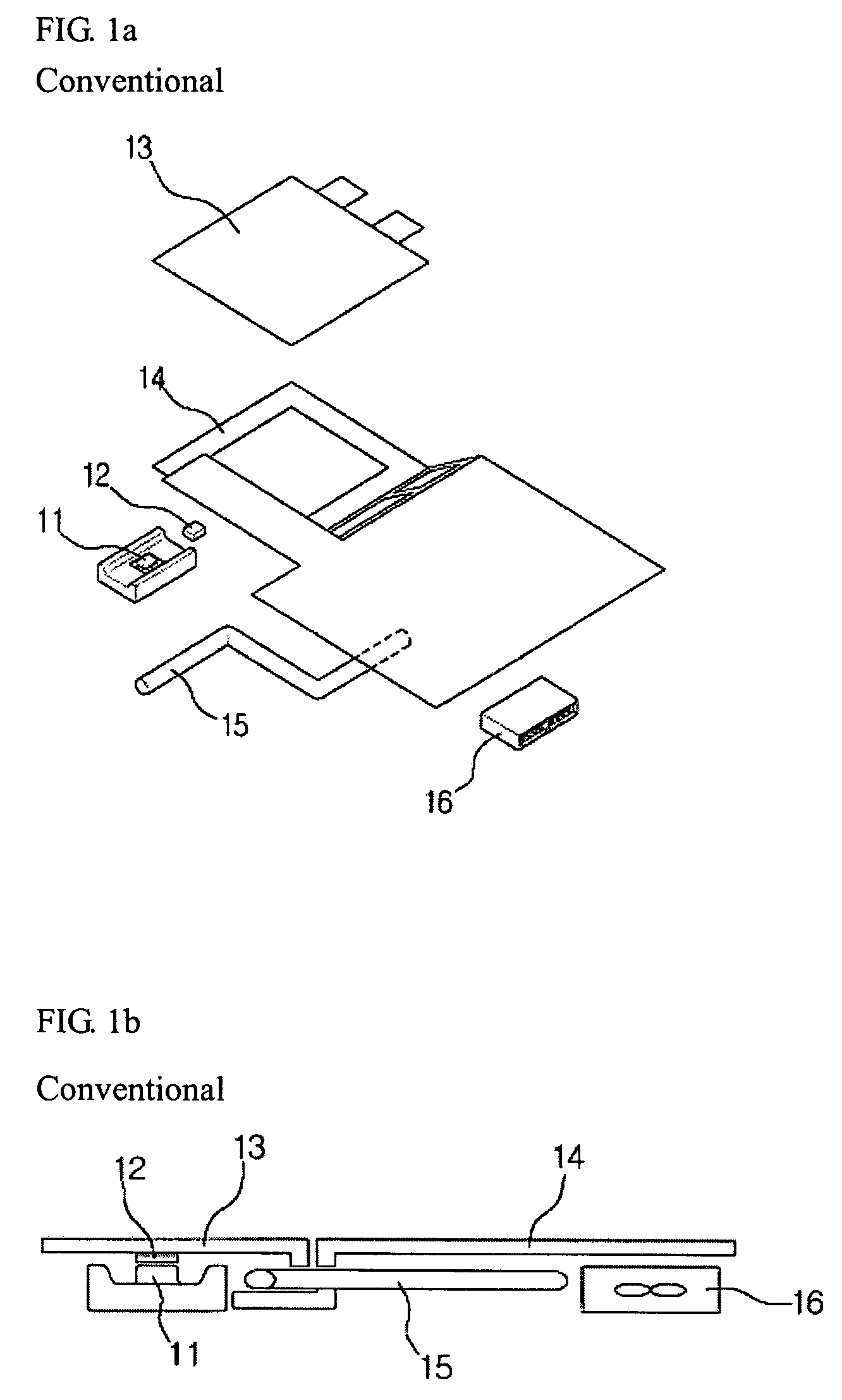
In the conventional dissipating structure of the notebook computer, the thermal pad 12 attached to the upper surface of the CPU 11 should stick to the first dissipating plate 13, but sticking process is cumbersome because a screw is used upon installation.
Further, since the dissipating plate is divided into two elements 13 and 14 that are connected by the heat pipe, heat transfer area is reduced and dissipating efficiency is deteriorated.

Method used


Image

  • Cooling system for a portable computer
  • Cooling system for a portable computer
  • Cooling system for a portable computer

Examples


Embodiment Construction

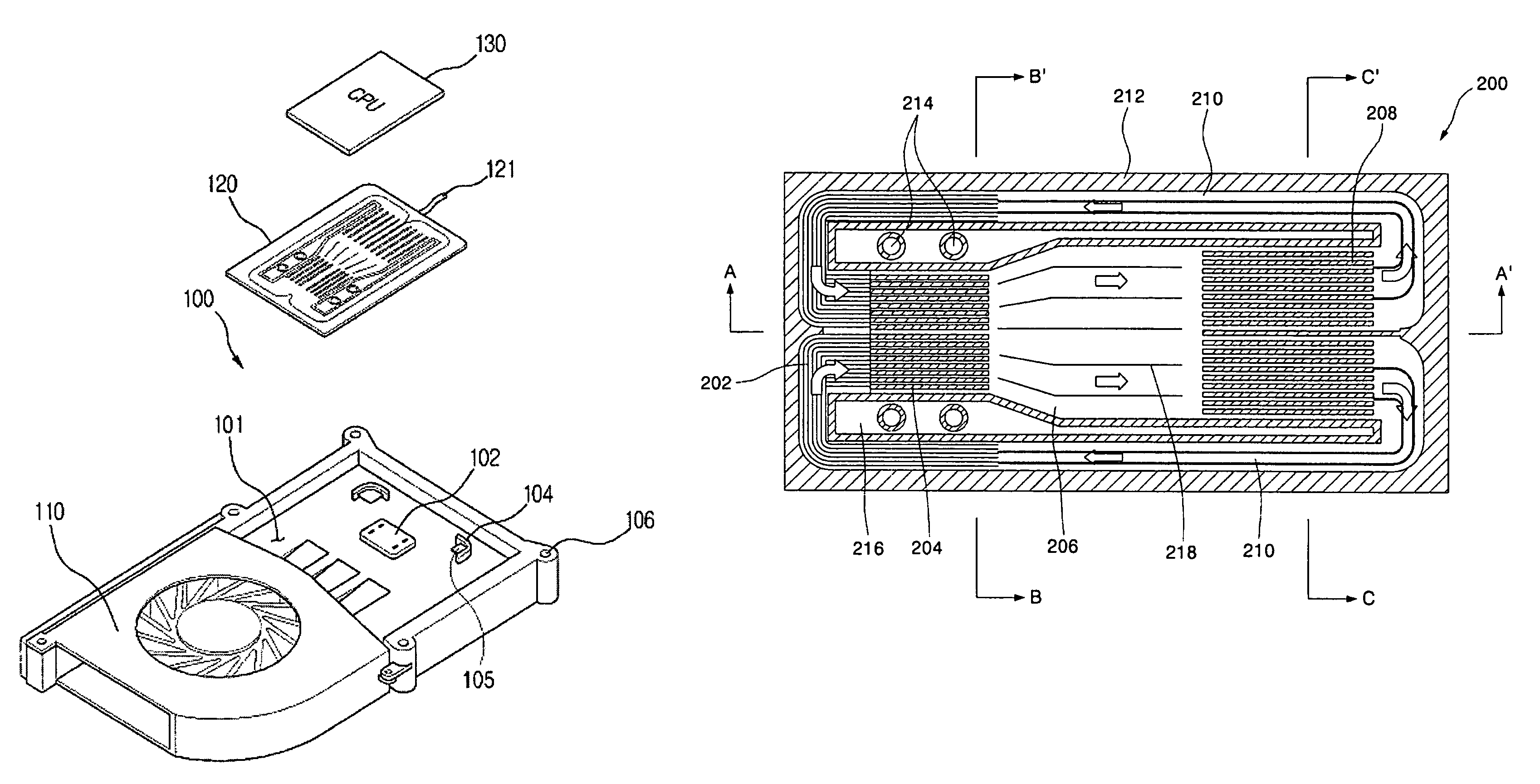
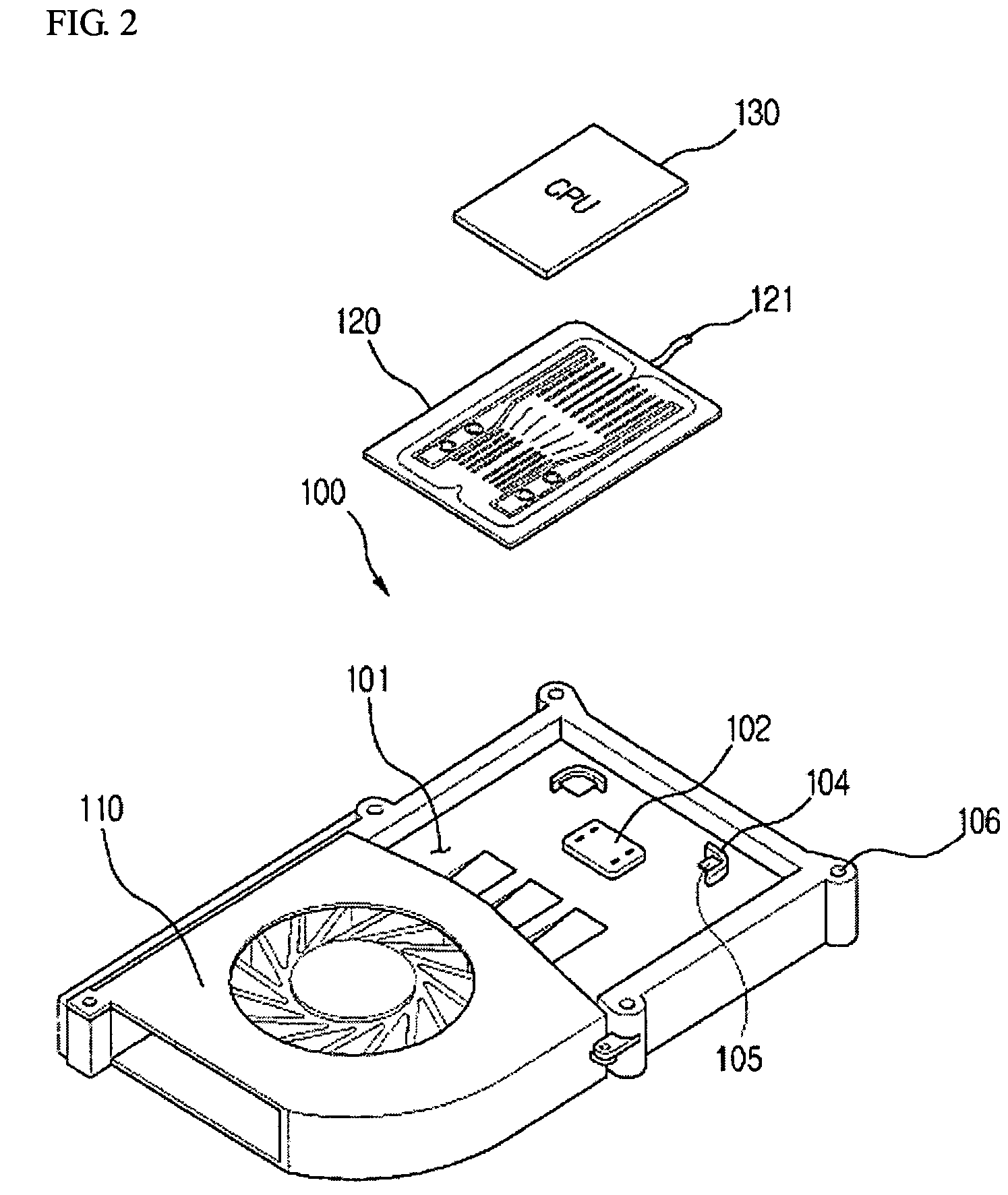
[0030]FIG. 2 is an exploded perspective view of a cooling system for use in a portable computer according to an embodiment of the present invention. FIG. 3 is a view showing an assembled state of the cooling system of FIG. 2.

[0031]As shown in FIGS. 2–4, an embodiment of a cooling system according to the present invention can include a dissipating plate or cooling unit 100 having a settle unit 102 and a guide protuberance 104 on its inner groove 101, a dissipating fan 110 joined to one side of the dissipating plate, a micro cooling system (MCS) 120, and a coil spring 108 and a screw 109 for giving elastic force when the dissipating plate 100 is mounted on the CPU of the main board. The MCS 120 can include a lower surface coupled to the upper surface of the settle unit 102 of the dissipating plate 100, and an upper surface faced with the CPU 130. The MCS 120 is a system that preferably has a cooling cycle for performing heat exchange by repeating condensation and evaporation of its ow...


PUM


Abstract

A cooling system for a portable computer can include a frame having a heat-source connecting unit in its one side and having a fan housing unit in its other side. A dissipating unit on one side of the fan housing unit performs heat exchange and a dissipating fan forms an air stream that can pass through the dissipating unit. A plate-shaped cooling unit coupled to one side of the frame can deliver heat from the heat-source connecting unit to the dissipating unit. The cooling unit can include a micro cooling unit that performs heat exchange using a cooling cycle through phase change or a plate-heat pipe filled with liquid. According to embodiments of the present invention, a thickness of the cooling system can be reduced and cooling capability efficiency can be increased.

Description

BACKGROUND OF THE INVENTION[0001]1. Field of the Invention[0002]The present invention relates to a cooling system for a portable computer.[0003]2. Background of the Related Art[0004]In a recently marketed notebook computer, a CPU (Central Processing Unit) is provided as a module and detachable from a connector installed on a main board. Since the CPU is provided as a module, the CPU can be upgraded or replaced if a new CPU module is brought to the market. According to the conventional art, upgrade was possible only for the desktop PC (Personal Computer). The notebook computer could not be upgraded because the CPU in the notebook computer was not detachable from the main board. However, an upgrade for a notebook computer has become possible because the CPU is now provided as a module.[0005]Since the CPU is provided as a module in the notebook computer there exists a need for an appropriate structure of a dissipating module for dissipating heat arising from the CPU during operations o...

Claims


Application Information

Patent Timeline
IPC IPC(8): H05K7/20F28D15/02H05K5/02G06F1/20H01L23/427H01L23/467
CPCF28D15/0233F28D15/046F28F13/06G06F1/203H01L23/427H01L23/467H01L2924/0002H01L2924/00
Inventor KIM, YE-YONGLEE, HARRISON FORDCHOI, JIN-KWAN
Owner LG ELECTRONICS INC
Learn More