
Low coherence interferometry utilizing phase

a phase and interferometer technology, applied in the field of low coherence interferometry of biological samples, can solve the problems of affecting the accuracy of the interferometer, and requiring relatively complex operations, and achieves enhanced facilitate the interference of the broadband light reflected, and enhance the effect of the interferometer

Inactive Publication Date: 2007-02-27
VZN CAPITAL
View PDF123 Cites 90 Cited by
  • Summary
  • Abstract
  • Description
  • Claims
  • Application Information

AI Technical Summary

Benefits of technology

"The patent text describes a method and system for measuring characteristics of an analyte in a biological sample using a broadband light source and a sensing light path. The method involves directing broadband light at the sample and receiving the reflected light from the sample and a reflecting device. The reflected light is then interfered with the light reflected from the reflecting device, and the resulting interference is detected. The system includes a modulator that modulates the effective light path length of at least one of the reference and sensing light paths to enhance interference. The system can determine the characteristic of the analyte based on the variation in index of refraction from the target depth and the phase component of the modulator function. The technical effects of this patent include improved accuracy and sensitivity in measuring the characteristics of analytes in biological samples."

Problems solved by technology

Diabetes can lead to severe complications over time, including heart failure, kidney failure, blindness, and loss of limb due to poor peripheral circulation.
Diabetes complications are largely due to years of poor blood glucose control.
This method is painful, requires relatively complex operations, is inconvenient due to disruption of daily life, and may become difficult to perform in the long term due to calluses on the fingers and poor circulation.
However, none of these procedures have achieved practical significance.
Large and costly equipment is required, which are wholly unsuitable for routine analysis or even for patient self-checking (home monitoring).
Several of these techniques are discussed herein as background, however, once again, none of these techniques has attained significant commercial success relative to invasive techniques.
Practical implementation of a glucose sensor based on these principles is very difficult and several wavelengths are required.
The Raman signal is very weak, requiring long data acquisition time, making the device sensitive to light source fluctuations.
Measurements are subject to high background noise because of tissue autofluorescence.
Scatter and reabsorption in biological tissues make detection of Raman frequency shifts due to physiological concentrations difficult.
Current instruments are complex and sensitive to environmental conditions.
The eye's aqueous humor has been suggested as the medium for this technique as skin is not a feasible site due to its high light scattering properties.
However, polarization measurements are affected by optical rotation due to cornea, and by other optically active substances.
However, techniques that rely on the backscattered light from the aqueous humor of the eye are affected by optical rotation due to cornea, and by other optically active substances.

Method used


Image

  • Low coherence interferometry utilizing phase
  • Low coherence interferometry utilizing phase
  • Low coherence interferometry utilizing phase

Examples


Embodiment Construction

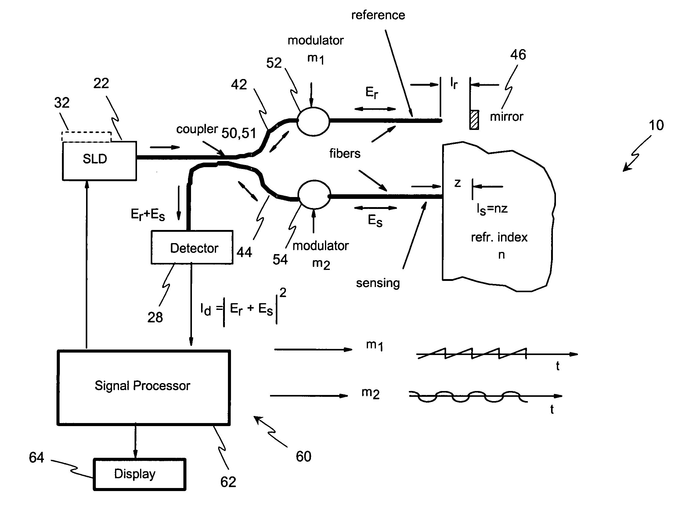
[0045]Disclosed herein, in several exemplary embodiments are high-sensitivity low coherence interferometric (LCI) systems (instruments) for optical metrology, which in an exemplary embodiment are miniaturized for use in a variety of sensing and monitoring applications, including, but not limited to, trace chemical sensing, optical properties and changes thereof, medical sensing such as non-invasive glucose monitoring and others. In an exemplary embodiment, the instrument is miniaturized, using integrated optics components such as waveguides, splitters and modulators on a single substrate such as, but not limited to, a LiNbO3 (Lithium Niobate) chip. The exemplary embodiments may also involve the use of a “circulator” type of optical component, including of a polarizing beam splitter and quarterwave plate, which can be combined with the light source and detector into a miniature module that prevents optical feedback into the light source while doubling the detected light. Alternativel...


PUM

PropertyMeasurementUnit
light wavelengthsaaaaaaaaaa
wavelengthaaaaaaaaaa
refractive indexaaaaaaaaaa

Abstract

A method for determining a characteristic of an analyte in a biological sample, the method comprising: directing broadband light by means of a sensing light path at the biological sample, at a target depth defined by the sensing light path and a reference light path; and receiving the broadband light reflected from the biological sample by means of the sensing light path. The method also includes: directing the broadband light by means of the reference light path at a reflecting device; receiving the broadband light reflected from the reflecting device by means of the reference light path; and interfering the broadband light reflected from the biological sample and the broadband light reflected from the reflecting device. The method further includes: detecting the broadband light resulting from interference of the broadband light reflected from the biological sample and the broadband light reflected from the reflecting device; and modulating an effective light path length of at least one of the reference light path and the sensing light path to enhance interference of the broadband light reflected from the biological sample and the broadband light reflected from the reflecting device. The method continues with: determining a magnitude of change of the effective light path length introduced by the modulating when interference is enhanced; determining a variation in an index of refraction from a ratio of the magnitude of change of the effective light path length and the target depth; and determining the characteristic of the analyte in the biological sample from the variation in the index of refraction.

Description

BACKGROUND[0001]The invention concerns a method for low coherence interferometry of a biological sample using phase. The term “biological sample” denotes a body fluid or tissue of an organism. Biological samples are generally optically heterogeneous, that is, they contain a plurality of scattering centers scattering irradiated light. In the case of biological tissue, especially skin tissue, the cell walls and other intra-tissue components form the scattering centers.[0002]Generally, for the qualitative and quantitative analysis in such biological samples, reagents or systems of reagents are used that chemically react with the particular component(s) to be determined. The reaction results in a physically detectable change in the solution of reaction, for instance a change in its color, which can be measured as a measurement quantity. By calibrating with standard samples of known concentration, a correlation is determined between the values of the measurement quantity measured at diff...

Claims


Application Information

Patent Timeline
Patent Type & Authority Patents(United States)
IPC IPC(8): G01B9/02A61B5/00G01N21/45G01N21/47G01N21/49
CPCA61B5/0066A61B5/14532A61B5/14546G01N21/49G01N21/45G01N21/474G01N21/4785A61B5/1455
Inventor ALPHONSE, GERARD A.
Owner VZN CAPITAL
Learn More