
Tangential force control in a touch location device

a technology of touch location and tangential force, applied in the field of touch sensors, can solve the problems of touch location error, touch location is typically misreported, and touch location is not applied straight against the touch surface, so as to reduce the exposure of force sensors to unnecessary stress, reduce the transmission of unmeasured components of force, and reduce the effect of effective application

Active Publication Date: 2007-02-27
3M INNOVATIVE PROPERTIES CO
View PDF42 Cites 60 Cited by
  • Summary
  • Abstract
  • Description
  • Claims
  • Application Information

AI Technical Summary

Benefits of technology

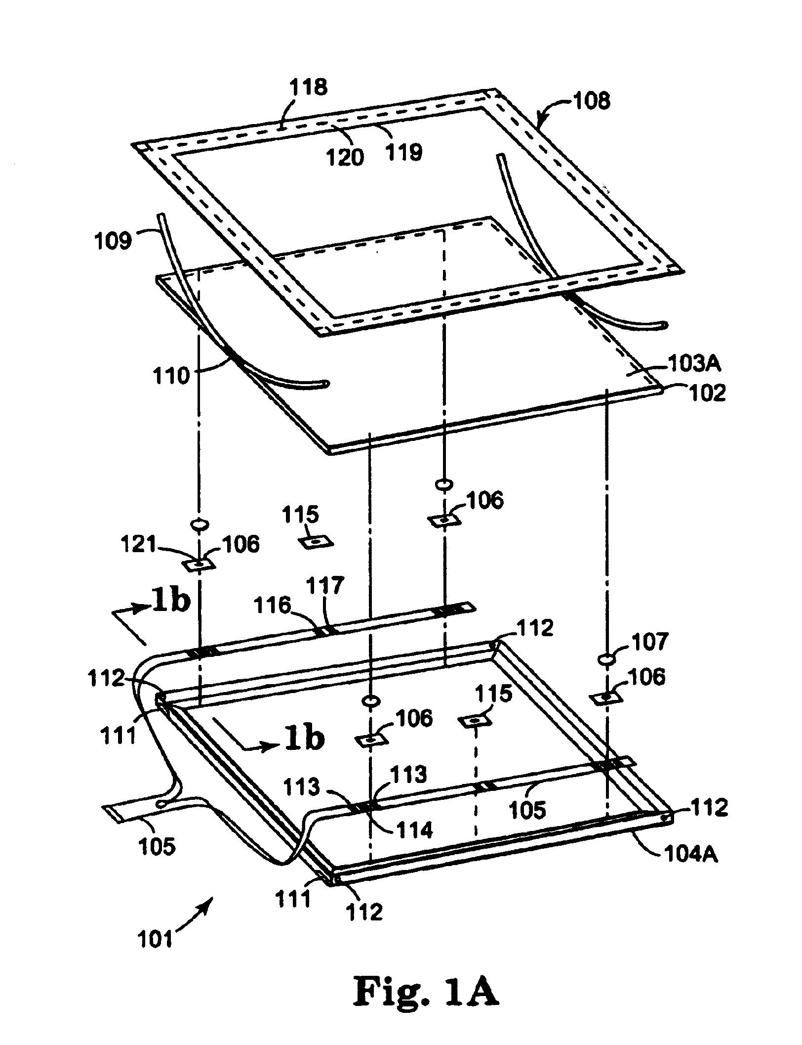
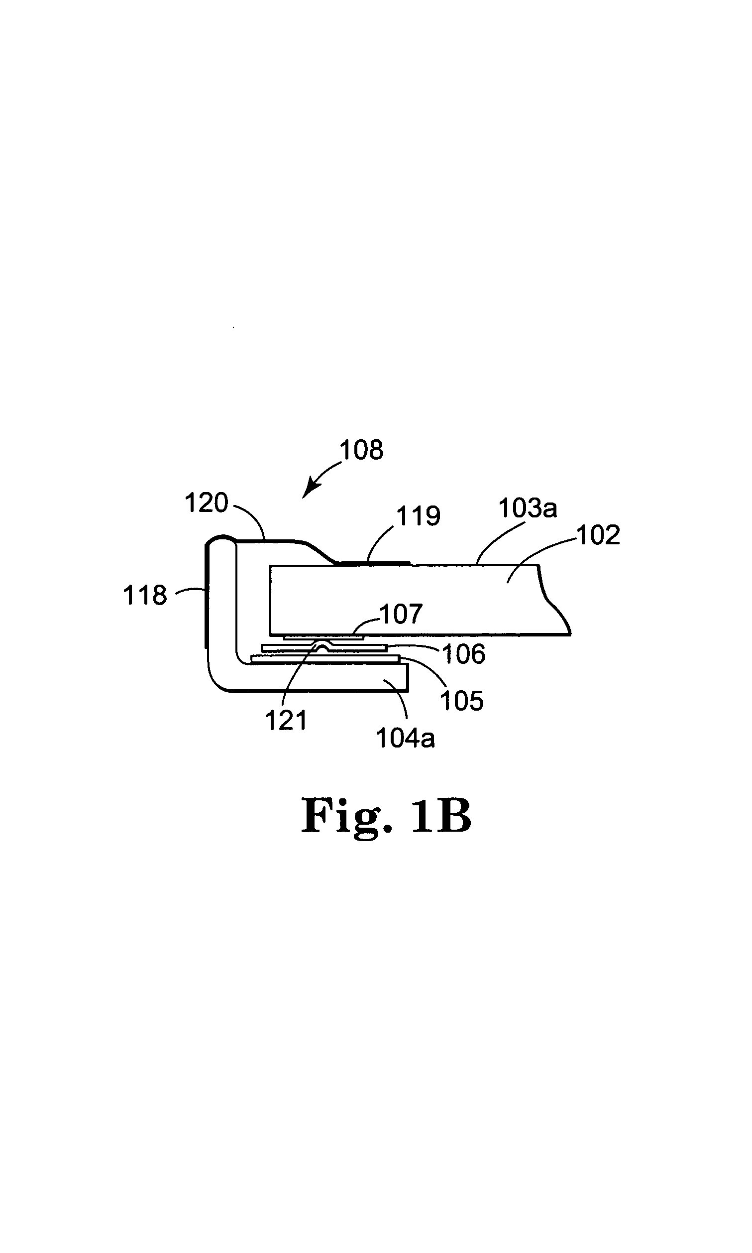
[0015]For example, in a first “divided paths” aspect of the invention, shunt connections may impede lateral motion of the touch surface structure at the level of the touch plane, and thereby reduce to insignificant magnitude reactions to tangential force passing through the sensing connections.
[0019]In yet another aspect of the invention, a lateral softening means may be employed within one or more sensor connections, to reduce the transmission of unmeasured components of force. This may aid in the effective application of other aspects of the invention, and may reduce exposure of force sensors to unnecessary stress.
[0020]In yet another aspect of the invention, a rotational softening means may be employed within one or more sensor connections, to reduce the transmission of unmeasured components of moment. Such unmeasured components of moment may contribute to touch location error, as they should be represented in the relevant moment equations. They are most likely to be both significant in magnitude, and unpredictable in character, when produced by a nearby touch flexing the touch surface structure. Rotational softening, especially when located close to the associated force sensor, may also reduce the exposure of that sensor to unnecessary stress.
[0021]In the divided path aspect of the invention, shunt connections may constitute a lateral stiffening means, dividing applied touch forces along two sets of force paths, one passing through the sensing connections, and one passing through the shunt connections. The shunt connections impede lateral motion of the touch surface structure at the level of the touch plane, and may thereby reduce to insignificant magnitude force transmitted through the sensing connections in response to tangential components of touch force. Sensor connections may be supplied with lateral softening means to enhance this effect. The shunt connections may be made perpendicularly soft, so as to divert the least amount of perpendicular touch force from the sensing connections. The shunt connections may also be sufficiently soft in rotation, such that essentially all resistance to rotation about axes in the touch plane is an expression of the perpendicular stiffness of the sensor connections. Since this last condition is readily met when the others are met, no special provisions may be required.
[0030]In a second embodiment, a set of displacement sensors detects perpendicular motions of portions of a rigid touch surface structure, effectively yielding a single, multiple-output sensing connection.

Problems solved by technology

One problem with conventional touch location devices is that they typically misreport the location of touches that are not applied straight against the touch surface.
In other words, if a user touches a touch surface with a finger or a stylus applying force at an angle other than 90 degrees to the touch surface, the location of the touch is typically misreported.
Errors in touch location may occur if the force sensor is sensitive to this combination.
All of these prior art approaches have drawbacks.
Ignoring tangential error may be unsatisfactory in precision applications, such as handwriting recognition, even when rearward sensor displacement is no more than the thickness of a 1 mm overlay.
Removing tangential error by placing the sensors in the plane of touch may be unsatisfactory for reasons of device width and thickness.
Pivoting the force transmission in the plane of touch, as disclosed by DeCosta, limits tangential error, but fails to address device width and thickness problems.
Measuring all degrees of freedom, as disclosed in Roberts, limits tangential error, but requires additional space and additional complexity somewhere within the device.
Thus it is seen that the prior art fails to teach how force sensors may be located behind the plane of touch without either excessive error, excessive bulk, or excessive cost.
Such unmeasured components of moment may contribute to touch location error, as they should be represented in the relevant moment equations.
They are most likely to be both significant in magnitude, and unpredictable in character, when produced by a nearby touch flexing the touch surface structure.

Method used


Image

  • Tangential force control in a touch location device
  • Tangential force control in a touch location device
  • Tangential force control in a touch location device

Examples


first embodiment

[0106]In a first embodiment, the elastic means 1010 is a beam of uniform modulus and moment of inertia, with portions 1010a and 1010b being of equal length. By symmetry, it may be seen that in this embodiment elastic means 1010 has an inflection point 1012, about which there is no moment produced in response to tangential forces that are applied to the touch surface 1006.

second embodiment

[0107]In a second embodiment, turning to FIG. 7B, portions 1020a and 1020b of elastic member 1014 are each separately beams of uniform modulus and moment of inertia, but with different moments of inertia having a constant ratio, independent of the defining transverse axis. If the ratio of the lengths of the two portions 1020a–b is set to the square root of the ratio of their moments of inertia, then there will again be an inflection point at 1012. Thus, for example, elastic member 1014 may have a round section. It may extend with diameter D for 200 mils below plane of touch 1006, and with diameter D / 2 for 50 mils above. With an appropriate choice of material and diameter D, elastic member 1014 may be of satisfactory strength, and yet be flexible enough to control the position of inflection point 1012. To accommodate the effect of flexure in surrounding structures however, it may be desirable to make empirical adjustments to the length of portion 1020a.

[0108]This method for achievin...


PUM


Abstract

Various techniques are provided for reducing the impact of tangential forces on touch location in a touch location device. For example, in one aspect, shunt connections are provided that impede lateral motion of the touch surface structure at the level of the touch plane, thereby reducing to insignificant magnitude reactions to tangential force passing through the sensing connections. In another aspect, sensing connections incorporate elastic means so adjusted as to turn that connection's reaction to tangential touch force perpendicular to its axis of sensitivity. In another aspect, sensing connections incorporate sensing means so adjusted as to turn that connection's axis of sensitivity perpendicular to its reaction to tangential force.

Description

CROSS REFERENCE TO RELATED APPLICATIONS[0001]This application is related to concurrently filed and commonly owned patent application entitled “Method and Apparatus for Force-Based Touch Input,” hereby incorporated by reference in its entirety.BACKGROUND[0002]1. Field of the Invention[0003]The present invention relates to touch sensors and, more particularly, to force sensing touch location devices for accurately locating touch forces that include tangential force components.[0004]2. Related Art[0005]The ability to sense and measure and / or locate a force applied to a surface is useful in a variety of contexts. As a result, various systems have been developed in which force sensors are used to measure properties of a force (referred to herein as a “touch force”) applied to a surface (referred to herein as a “touch surface”). In response to the touch force, force sensors typically generate signals that may be used, for example, to locate the position on the touch surface at which the t...

Claims


Application Information

Patent Timeline
Patent Type & Authority Patents(United States)
IPC IPC(8): H03M11/00G06F3/041
CPCG06F3/0414G06F3/04142G06F3/041G06K11/06
Inventor ROBERTS, JERRY B.
Owner 3M INNOVATIVE PROPERTIES CO
Learn More