
Light appliance and cooling arrangement

Inactive Publication Date: 2007-02-27
S R SMITH
View PDF11 Cites 14 Cited by
  • Summary
  • Abstract
  • Description
  • Claims
  • Application Information

AI Technical Summary

Benefits of technology

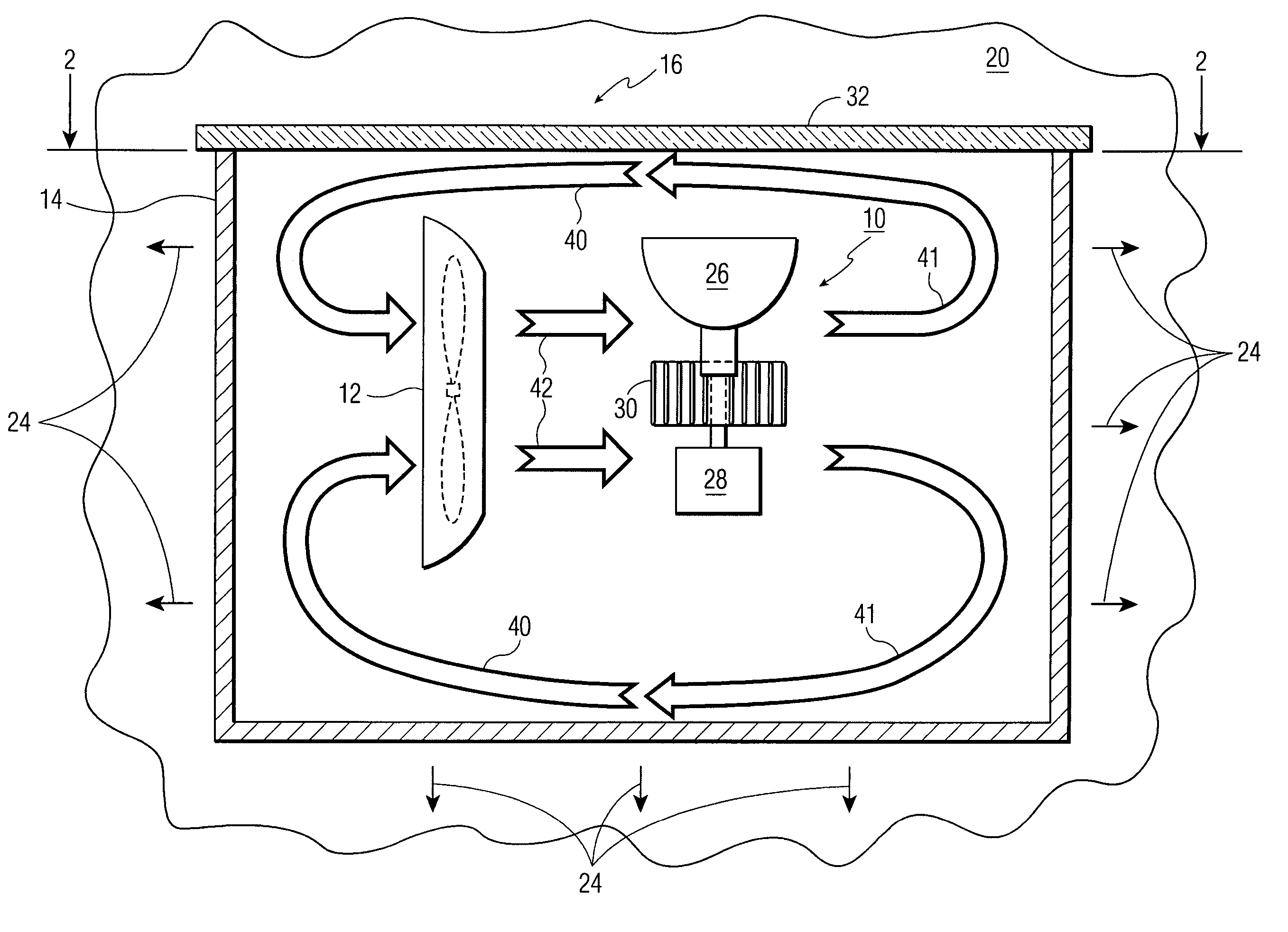
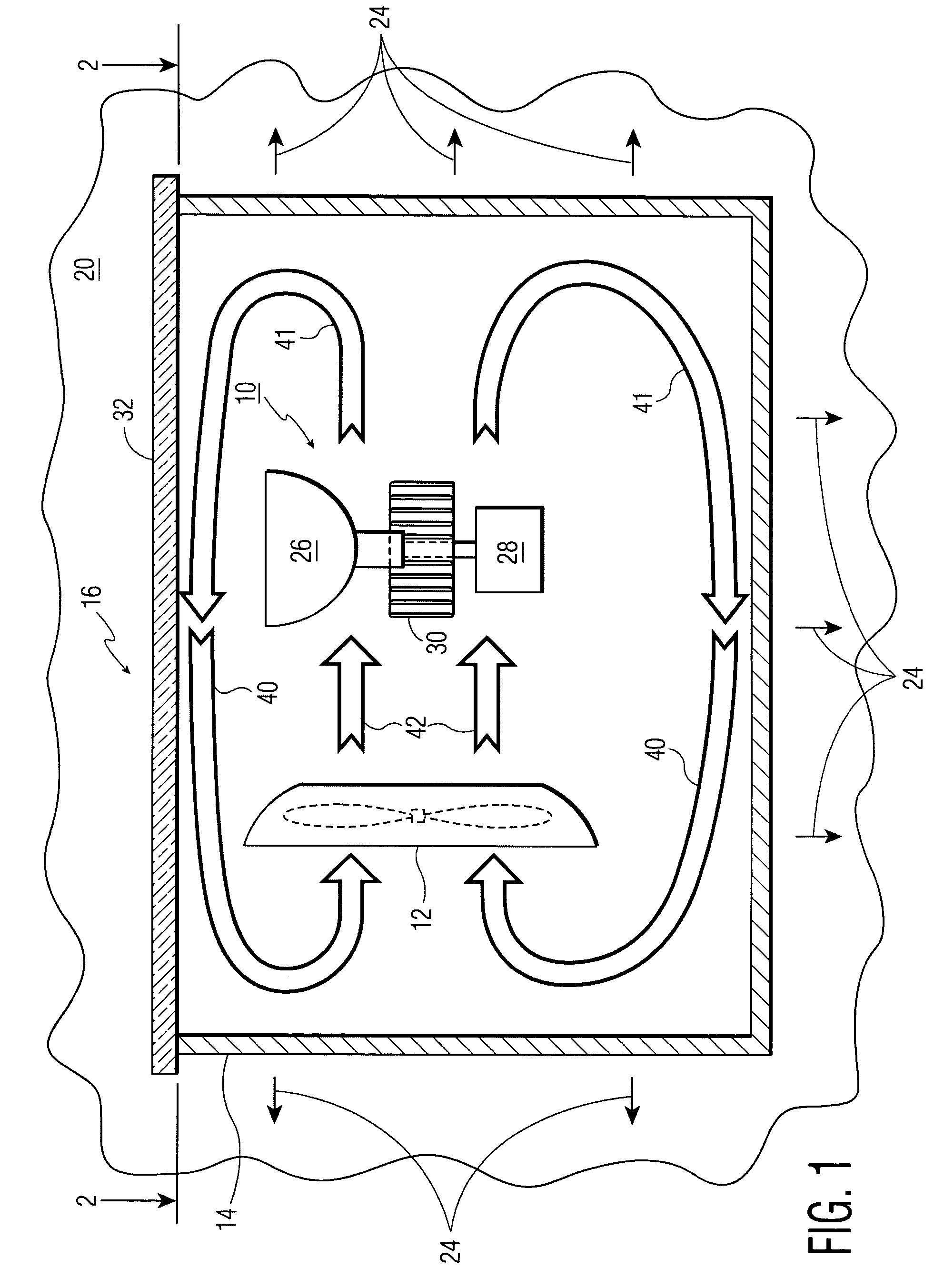
[0009]The foregoing combination effectively cools a light appliance within a substantially sealed enclosure.

Problems solved by technology

This has the effect of reducing the lamp life to the point where the lamp is non-viable for consumer use.
These foils are at risk of premature oxidation if operated at high temperatures.
The premature oxidation of the molybdenum lamp connections results in early lamp failure.
The main cause of the source's temperature rise is the inability to remove heat from the source and from the sealed environment, and then to supply cooler air to the light source.

Method used


Image

  • Light appliance and cooling arrangement
  • Light appliance and cooling arrangement
  • Light appliance and cooling arrangement

Examples


Embodiment Construction

[0014]This description covers the three points of (1) general principles of the invention, (2) alternative cooling mediums that may be used, and (3) specific light appliance thermal issues.

1. General Principles

[0015]The first part of these General Principles does not refer to the drawings.

[0016]Optionally incorporating a heat sink for a light source component increases thermal mass and reduces the overall temperature of the component. By having a larger surface area, it is easier for thermal energy, which is to be dissipated away from the component, to be cooled through conduction with stagnant air, or through convection if used with a fan. To maximize the cooling effect, a heat sink could be used in conjunction with a cooling fan. Occasionally, a high power lamp will have metal connectors on the end(s) of the lamp which can also act as heat sinks.

[0017]To effectively use a cooling fan within a sealed environment, some portion or all of the walls of the sealed environment are therma...


PUM


Abstract

Disclosed is a light appliance and a cooling arrangement, comprising a light appliance and a substantially sealed enclosure for the light appliance that gives off unwanted heat into surrounding air within the enclosure during operation. The enclosure has an external wall at least part of which is thermally conductive. A medium, cooler than the external wall of the enclosure, contacts the external wall. An air circulating device is provided for circulating air, heated by the electrical appliance or by the air circulating device, to the thermally conductive portion of the external wall for removing heat from the air by thermally dissipating the heat into the cooler medium through said thermally conductive portion.

Description

[0001]This application claims priority from U.S. Provisional Application No. 60 / 452,729 filed Mar. 7, 2003.FIELD OF THE INVENTION[0002]The present invention relates to an light appliance contained within a substantially sealed enclosure and an associated cooling arrangement for removing unwanted heat generated by the light appliance. This increases the operating lifetime of the light appliance.BACKGROUND OF THE INVENTION[0003]By sealing a light source within an enclosed environment, the operating temperature of the source is seen to increase dramatically over its designed lifetime for an open-air operating temperature. This has the effect of reducing the lamp life to the point where the lamp is non-viable for consumer use. This is a particular concern for halogen and metal halide lamps, which use molybdenum foils to make electrical connections. These foils are at risk of premature oxidation if operated at high temperatures. The premature oxidation of the molybdenum lamp connections ...

Claims


Application Information

Patent Timeline
IPC IPC(8): F21V29/00F21V29/02
CPCF21V29/677F21V29/004F21Y2101/02F21W2131/401F21Y2115/10F21V29/74
Inventor BUELOW, II, ROGER F.DAVENPORT, JOHN M.LIN, DAVID Y.
Owner S R SMITH
Learn More