
Frequency doubler circuit with trimmable current control

a frequency doubler and current control technology, applied in the field of frequency doubler circuits with trimmable current control, can solve the problems of not being able to generally adjust the current charging of capacitors, often varied capacitors, waste of parts, etc., and achieves accurate duty cycle, high frequency signal precision, and fewer parts.

Active Publication Date: 2007-02-20
MONTEREY RES LLC
View PDF5 Cites 69 Cited by
  • Summary
  • Abstract
  • Description
  • Claims
  • Application Information

AI Technical Summary

Benefits of technology

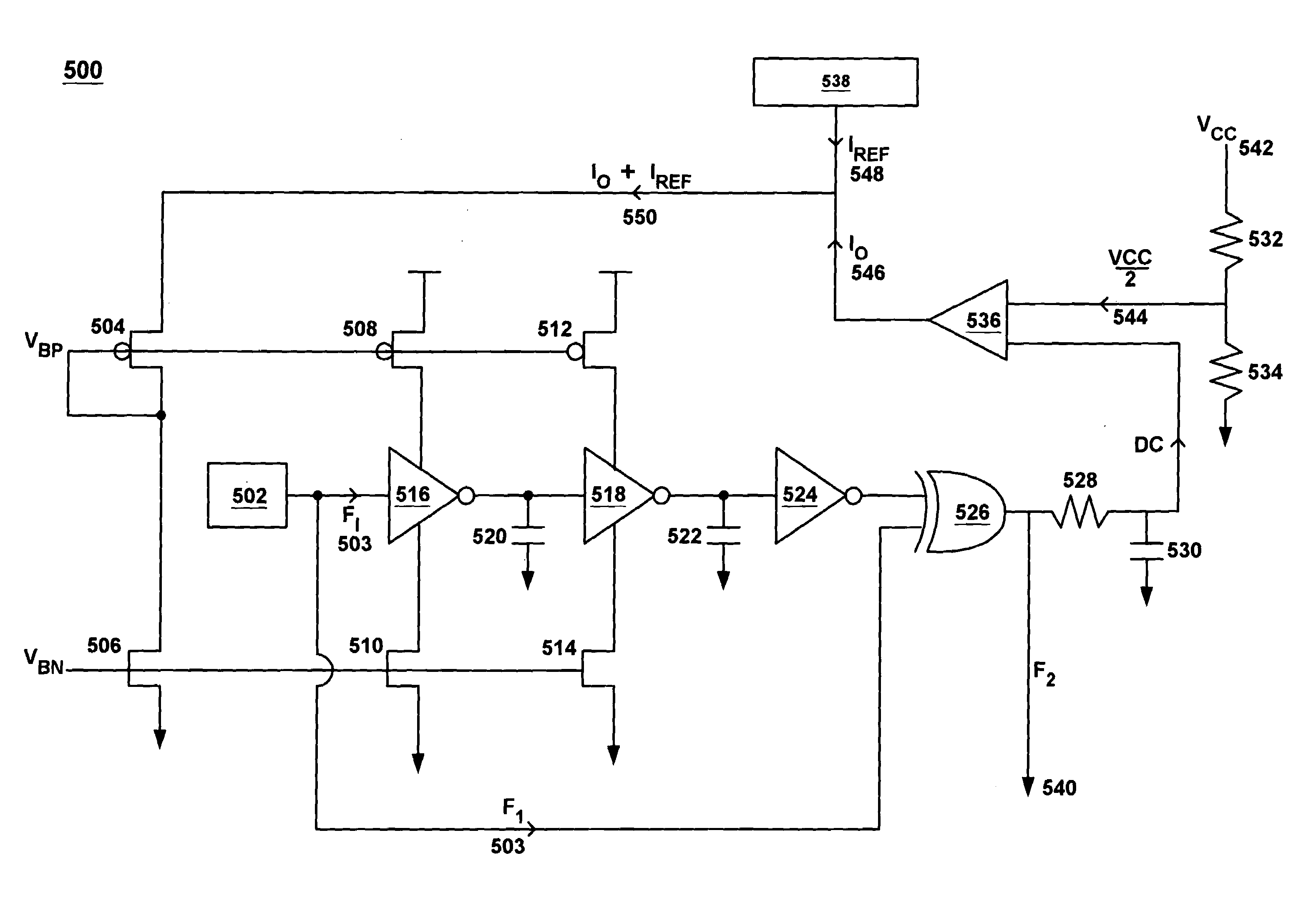
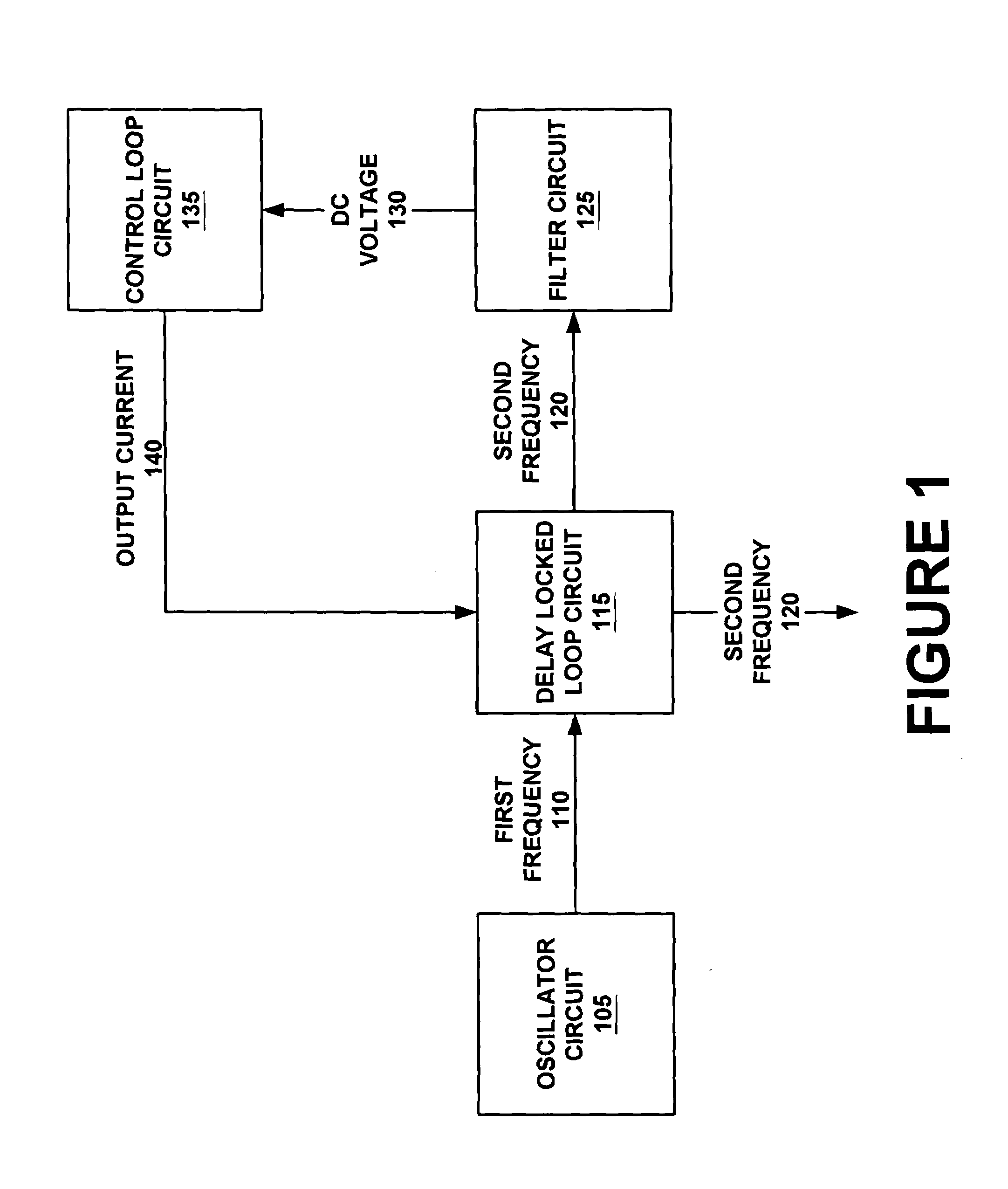
"The present invention provides a frequency douler circuit that can account for variations in capacitance without requiring external capacitors. It also allows for a more accurate duty cycle and requires fewer parts, making it less expensive. The circuit includes an oscillator and a frequency douler circuit with a current source and a reference current. The reference current compensates for variations in capacitance and helps maintain a known duty cycle, resulting in higher frequency signal precision. The circuit can be used in microcontrollers and other electronic devices."

Problems solved by technology

A disadvantage to the use of capacitors is that capacitors often vary due to the fabrication process or to temperature.
In current frequency doubler circuits, it is not always of generally possible to adjust the current charging the capacitors to account for process variation.
In order to ensure that capacitors are to the proper specifications, all capacitors should be tested and those that are not to specification are discarded, resulting in wasted parts.
Conventional frequency doubler circuits do not provide a highly controlled duty cycle as they do not compensate for capacitor process variation.

Method used


Image

  • Frequency doubler circuit with trimmable current control
  • Frequency doubler circuit with trimmable current control
  • Frequency doubler circuit with trimmable current control

Examples


Embodiment Construction

[0025]Reference will now be made in detail to the preferred embodiments of the invention, examples of which are illustrated in the accompanying drawings. While the invention will be described in conjunction with the preferred embodiments, it will be understood that they are not intended to limit the invention to these embodiments. On the contrary, the invention is intended to cover alternatives, modifications and equivalents, which may be included within the spirit and scope of the invention as defined by the appended claims. Furthermore, in the following detailed description of the present invention, numerous specific details are set forth in order to provide a thorough understanding of the present invention. However, it will be obvious to one of ordinary skill in the art that the present invention may be practiced without these specific details. In other instances, well-known methods, procedures, components, and circuits have not been described in detail so as not to unnecessarily...


PUM


Abstract

A frequency doubler circuit with trimmable current control. In one embodiment, the present invention provides a circuit comprising an oscillator with a current source and a frequency doubler circuit coupled to the current source. In one embodiment, the current source is for generating a reference current. In one embodiment, the frequency doubler circuit is operable to receive a first frequency signal for generating a second frequency signal and also receiving the reference current. The frequency doubler circuit, using the reference current, operates to compensate for process variation of capacitance of the frequency doubler circuit and uses the reference current to maintain a known duty cycle. In one embodiment, the circuit further comprises a control loop for generating an output current, wherein the output current, operating in conjunction with the reference current, operates to compensate for process variation of capacitance of the frequency doubler circuit and uses the reference current to maintain a known duty cycle. In one embodiment, the current source comprises a trimmable current control.

Description

RELATED U.S. APPLICATION[0001]This application claims priority to the copending provisional patent application Ser. No. 60 / 243,708, entitled “Advanced Programmable Microcontroller Device,” with filing date Oct. 26, 2000, and assigned to the assignee of the present application.FIELD OF INVENTION[0002]The present invention relates to the field of semiconductor devices. More particularly, the present invention relates a frequency doubler circuit with trimmable current control.BACKGROUND OF THE INVENTION[0003]Oscillator circuits are used with digital electronic circuits (e.g., microcontrollers and microprocessors) for a variety of uses including to generate a clock signal (e.g., a frequency signal) for synchronizing, pacing and coordinating the operations of the digital electronic circuit. Some common forms of oscillator circuits are crystal oscillator circuits and voltage controlled oscillators (VCO) circuits.[0004]Often, it is desirable to generate a frequency signal that is double th...

Claims


Application Information

Patent Timeline
Patent Type & Authority Patents(United States)
IPC IPC(8): H03B19/14
CPCH03B19/14
Inventor SHUTT, JAMESKUTZ, HAROLD
Owner MONTEREY RES LLC
Learn More