Speaker for vehicle and mounting structure of the speaker

a technology for vehicle speakers and mounting structures, which is applied in the direction of piezoelectric/electrostrictive transducers, transducer types, transportation and packaging, etc., can solve the problems of increasing the number of parts, high manufacturing cost, and requiring a large amount of man-power for the installation of the speaker unit, so as to improve the installation efficiency, reduce the sliding resistance at rotation, and improve the acoustic characteristic

Active Publication Date: 2007-02-13
MITSUBISHI MOTORS CORP
View PDF17 Cites 19 Cited by
  • Summary
  • Abstract
  • Description
  • Claims
  • Application Information

AI Technical Summary

Benefits of technology

[0052]The interposition of the above-mentioned rubber-made sealing member reduces the sliding resistance at rotation with respect to a sponge, which has been used so far, thereby improving the installation efficiency.
[0053]Add to it that, although the fo...

Problems solved by technology

However, this installation structure requires the employment of the grommets 102 because consideration is given to the generation of rust in the speaker unit attaching section, which leads to an increase in number of parts.
In addition, this requires a large amount of man-power for the installation of the speaker unit 101.
(1) a high manufacturing cost;
(2) a long assembling time;
(3) a requirement for precise alignment between the screw holes 101a of the speaker unit 101 and the grommets 102, which lowers the working efficiency or workability; and
(4) a need for a worker to operate while holding the speaker unit 101, the screws 103 and a tool (driver) simultaneously, which lowers the productivity.
However, the technique disclosed in the above-mentioned Japanese Patent Laid-Open No. 2001-169374 creates the following problems.
Moreover, for the acoustic characteristic, it is desirable that the opening area is large, but this disagrees with it.
Moreover, in the above-described conventional speaker installation structure, as a problem, working holes or the like for installation are not made particularly around the speaker unit, so it is not ea...

Method used


Image

  • Speaker for vehicle and mounting structure of the speaker
  • Speaker for vehicle and mounting structure of the speaker
  • Speaker for vehicle and mounting structure of the speaker

Examples


Embodiment Construction

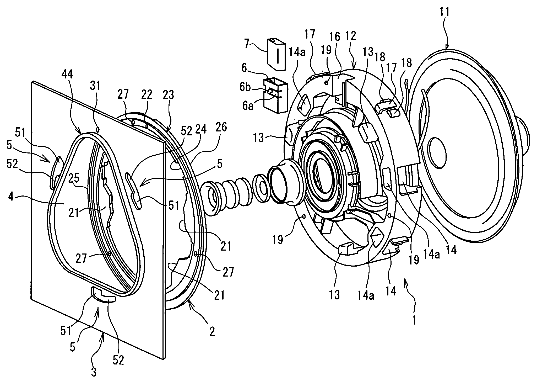
[0107]An embodiment of the present invention will be described hereinbelow with reference to the drawings. In FIGS. 1 to 3, reference numeral 1 designates a speaker unit, numeral 2 represents a sealing member, and numeral 3 denotes a door inner panel acting as a panel member. The speaker unit 1 is mainly composed of a speaker body (which will hereinafter be referred to simply as a “speaker”) 11 and a speaker housing (which will hereinafter be referred to simply as a “housing”) 12 for holding the speaker 11, with functional parts such as coils being held in the housing 12.

[0108]In addition, in this embodiment, the housing 12 is made of a resin as one-body construction, and as shown in FIGS. 2, 8, 9 and 14, on the rear surface side of the housing 12, there are formed a plurality of claws 13 for fixedly securing the speaker unit 1 to the door inner panel 3.

[0109]Still additionally, as FIGS. 1 to 3 show, in the door inner panel 3 on which the speaker unit 1 is mounted, there is made an ...


PUM


Abstract

The present invention relates to a speaker for a vehicle and an installation structure therefor, and it is an object of the invention to enhance the speaker installation rigidity without impairing the acoustic characteristic of the speaker. The speaker installation structure comprises a speaker unit (1) for holding a speaker body (11) and having a plurality of claws (13) and a panel member (3) having an opening (4) and a plurality of slits (5). For the installation of the speaker unit (1), the plurality of claws (13) are inserted into the plurality of slits (5), respectively, and the speaker unit (1) is rotated in its circumferential direction. The opening (4) is made to be smaller than the diameter of a speaker housing (12) and to have at least three linear portions (41). Each of the slits (5) is formed outside the three linear portions (41) and inside an outer circumference of the speaker housing (12).

Description

[0001]This application is the national phase under 35 U.S.C. § 371 of PCT International Application No. PCT / JP02 / 11367 wich has an International filing date of Oct. 31, 2002, which designated the United States of America.TECHNICAL FIELD[0002]The present invention relates to a speaker for a vehicle and an installation structure therefor, made to be installed in the interior of the vehicle such as a car.BACKGROUND ART[0003]So far, a speaker has been attached onto a door, rear shelf or the like of a car. With reference to FIG. 23, a description will be given herein below of one example of an installation structure of a speaker. In a door panel 104 of a car, there is made an opening 105 which is used for mounting a speaker unit 101.[0004]At predetermined positions around this opening 105, a plurality of fitting holes 104a are formed to accept grommets 102 to be threadly engaged with small screws 103.[0005]Accordingly, a worker aligns screw holes 101a made in the speaker unit 101 with th...

Claims


Application Information

Patent Timeline
IPC IPC(8): H04R25/00B60R11/00B60R11/02H04R1/02
CPCB60R11/0217H04R1/025B60R2011/0047B60R2011/0061B60R2011/0059B60R11/02
Inventor IWAYA, SHOGONAKASHIMA, SUKEYOSHINAKAMURA, TAIZOKIRIHARA, KAREBU
Owner MITSUBISHI MOTORS CORP
Why Eureka
Try Eureka