Stent graft with improved proximal end

Active Publication Date: 2007-02-13
WILLIAM A COOK AUSTRALIA +1
View PDF11 Cites 202 Cited by
  • Summary
  • Abstract
  • Description
  • Claims
  • Application Information

AI Technical Summary

Benefits of technology

[0006]The foregoing problems are solved and a technical advance is achieved in an illustrative intraluminal prosthesis, such as a stent graft, made of a sleeve of material (e.g., a tight-mesh fabric, extruded polymer, and / or a biomaterial) which includes a leading edge portion having an external structure configured to prevent anchoring stent detachment and / or leakage of blood or fluids around the 
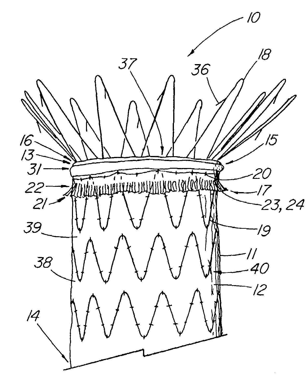
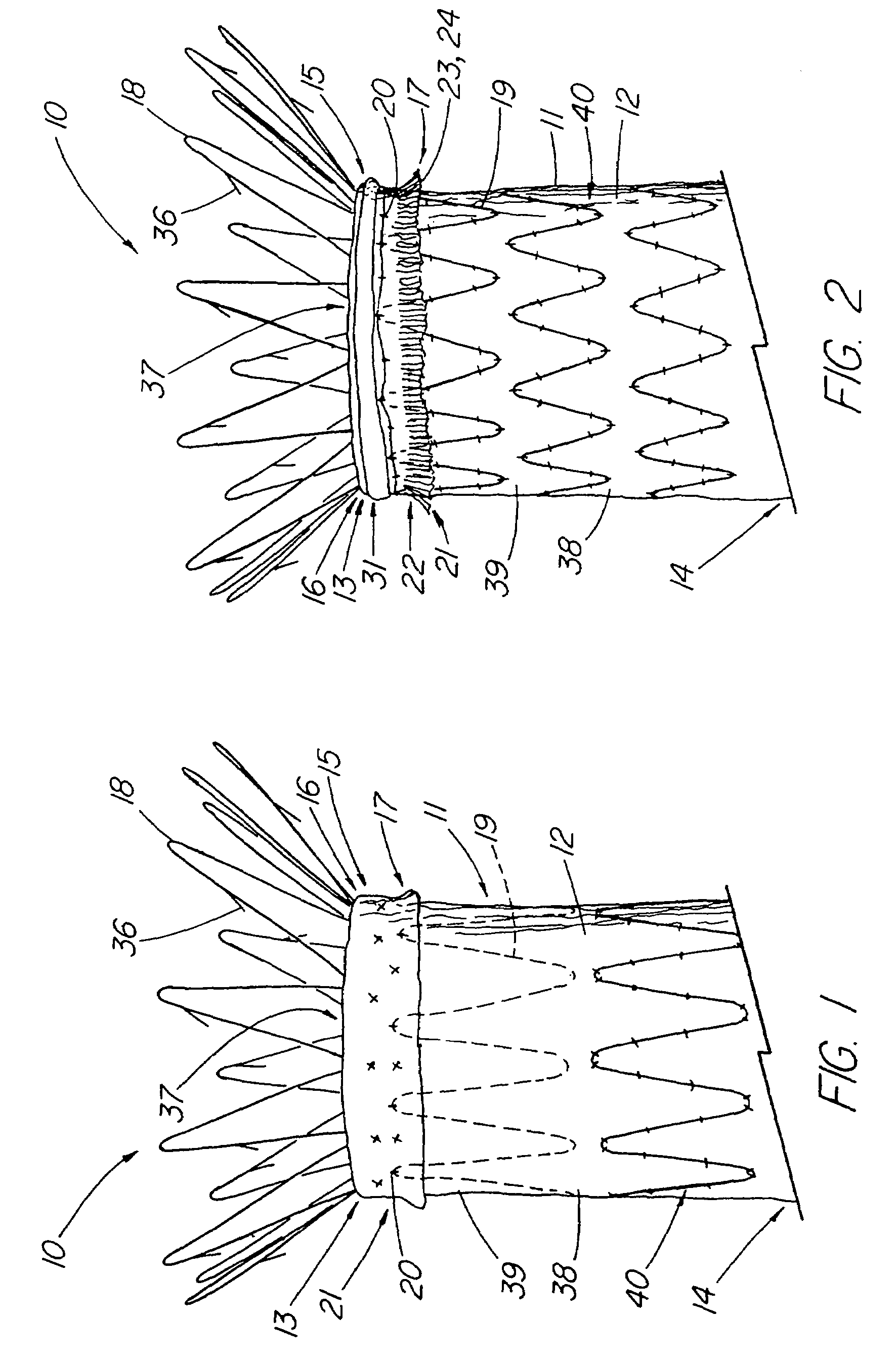
graft portion. In one aspect of the invention, the stent graft includes a proximal cuff portion to which at least the proximal stent may be attached, thereby providing at least a first and second layer of material that helps provide a more secure substrate for the attached stent(s). The double layer is more likely to hold the sutures and keep them intact, as well as being less likely to have a portion of the stent wear through the fabric over time. A first illustrative embodiment comprises a stent graft adapted for use in treating an aortic aneurysm, such as the ZENITH® AAA Endovascular Graft, in which the most proximal stent extends beyond the proximal or top edge of the graft potion to help anchor the stent graft in the vessel. The prosthesis is placed at or above the iliac bifurcation with the proximal stent acting as a suprarenal stent, attaching to the healthy portion of the aorta about and above the openings to the renal arteries. Because this particular stent typically is only attached about the distal bends and strut portions, there are relatively few sutures to anchor the stent to the material. The cuff of the present invention gives a double-thickness layer of graft material, such as DACRON® polyester fiber (trademark of EI duPont de Nemours & Co., Inc.) for holding the sutures intact and providing better assurance that the distal bends or struts of the zig-zag stent will not wear through the fabric, creating a hole or causing detachment of the suprarenal stent at that point.
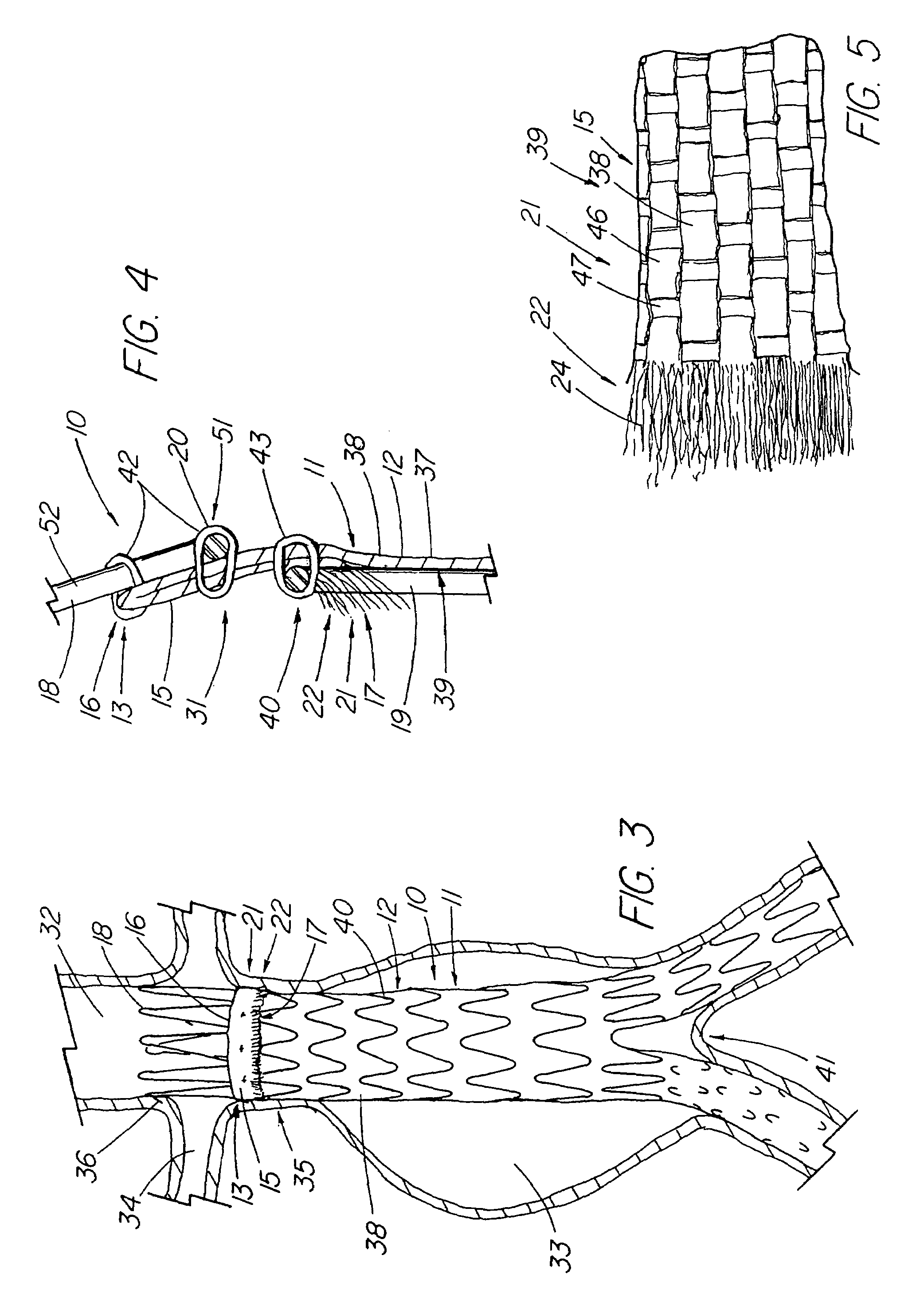
[0007]The stent adjacent to the proximal anchoring (suprarenal) stent may also be partially attached to the cuff as well. The proximal stent can be sewn to the cuff from the inside or the outside of the graft, preferably, but not necessarily to both the main body and cuff portions. Additionally, the stent can be sewn to the graft material's folded or leading edge such that the stent and graft material generally abut one another. This reduces thickness by not having the struts of the stent overlapping the material. Furthermore, the cuff can comprise a separate piece of the same or a different material that is sewn, bonded, applied, or otherwise attached to the main body of the graft with the anchoring stent or other supporting structure being attached to both layers to provide added support. While the cuff preferably encircles the entire circumference of the main body of the graft, it is within the scope of the invention (and definition of the term ‘cuff’) to include a series of discrete cuff ‘flaps’ or patch-like elements distributed around the circumference of the main body as points to which the bends or struts of the anchoring stent or other supporting structure are attached.
[0009]In another aspect of the invention, the cuff, which comprises a first edge at the leading or folded edge of the graft extending to second edge that comprises the free or cut edge of the material, is adapted to extend outward to serve as an external sealing zone to engage the vessel wall and help prevent leakage of blood or fluid around the device. In one illustrative embodiment of a modified ZENITH® AAA Endovascular Graft, approximately 10 mm of the graft material is folded over on itself such that the free edge is on the outside of the graft. Approximately the distal 5 cm of the cuff includes a region in which the threads and fibers of the DACRON® polyester fabric have been at least partially separated from one another to create a frayed region that extends outward from the graft and facilitates sealing by encouraging thrombus formation and tissue ingrowth. Graft material, such as DACRON® polyester fiber, is particularly well-suited to form thrombus. One advantage of the external sealing zone is that the top or first supporting stent, which has the ability to compromise the quality of the graft-vessel seal if placed on the outside of the graft (such as is the case with the ZENITH® AAA Endovascular Graft), can be moved from the inside to the outside of the graft and still allow for adequate sealing. This allows the inner lumen of the graft to remain smooth and stent-free. In a variation of this embodiment, the frayed region is folded or otherwise directed so that it extends proximally, thereby creating a third layer of graft material along the first edge of the cuff. Additionally, the frayed region can be modified to enhance its sealing properties, such as by adding agents to encourage thrombosis or cell proliferation, adding structure capable of stimulating the cell injury response and facilitate tissue ingrowth.

Problems solved by technology

For stent grafts placed in the aorta, the pulsatile forces of blood being exerted on the device are sufficiently great such that over time, the sutures may break or pull through the material, which can cause the anchoring stent and graft to separate.
If this occurs, the device may migrate or shift, resulting in the aneurysm no longer being excluded and making a subsequent rupture of the aneurysm potentially lethal to the patient.
While endoleaks can occur anywhere where an aortic stent graft is placed, they can be particularly troublesome when the graft is placed to treat an aneurysm occurring in the region between the renal arteries and the iliac bifurcation.
If the neck of the aneurysm (the healthy portion or the vessel between the aneursymal sac and renal arteries) is short or tortuous in shape, it may be difficult to get proper alignment, anchoring, or a good seal between the graft and the vessel wall, possibly resulting in a Type I endoleak in which the sac may continue to be pressurized with blood.

Method used


Image

  • Stent graft with improved proximal end
  • Stent graft with improved proximal end
  • Stent graft with improved proximal end

Examples


Embodiment Construction

[0026]FIG. 1 depicts a graft prosthesis 10 that includes a graft portion 11 having a first end 13, which typically forms the proximal or leading edge of the main body 12 of the tubular graft portion, and a second end 14, which typically is the distal end which is further downstream from the direction of blood or fluid flow. The illustrative graft prosthesis 10 represents a modified ZENITH® AAA Endovascular Graft comprising a tubular graft portion 11 of DACRON® polyester fiber (including a bifurcated distal portion in this embodiment to feed into the right and left iliac arteries), and a supporting structure 40 that comprises a series of zig-zag stents sewn thereto, including a proximal anchoring stent 18, such as the illustrative suprarenal zig-zag stent with barbs, extending from the proximal (caudal) end to anchor the stent graft above the aneurysmal sac. The prosthesis 10 further includes a cuff portion 15 comprising material of the main body 12 that is folded over the outside th...


PUM


Abstract

Disclosed is a stent graft prosthesis comprising a graft portion that includes a main body portion and an cuff portion, the cuff portion generally located at or near the proximal end of the main body portion and extending circumferentially therealong. Stents comprising the graft supporting structure are also attached to graft portion about the proximal end. In one embodiment, the cuff portion comprises material that is folded over the outside surface of the main body portion with an anchoring stent being attached over the cuff and main body portions, extending proximally therefrom. In another series of embodiments, the cuff portion comprises an external sealing zone that extends around the outer main body portion to help prevent leakage of fluids. In one example, the material of the second edge of the cuff portion is frayed to better engage the vessel walls and promote thrombus and / or tissue growth.

Description

CROSS-REFERENCE TO RELATED APPLICATIONS[0001]This application claims priority of provisional application Ser. No. 60 / 404,662 filed Aug. 20, 2002. This application is related to the U.S. patent application Ser. No. 10 / 322,862 filed Dec. 18, 2002, entitled Stent Graft With Improved Adhesion.TECHNICAL FIELD[0002]This invention relates to medical devices and more particularly, to intraluminal graft prostheses.BACKGROUND OF THE INVENTION[0003]The top or proximal edge region of a graft prosthesis, particularly one used to exclude an abdominal aortic aneurysm (AAA) or an aneurysm within the thoracic arch, is that portion of the device which is perhaps most critical to clinical success. Typically, it is the portion of the graft that forms the critical seal against the walls of the aorta to prevent leakage of arterial blood directly into the aneurysmal sac (a situation known as a Type I endoleak). In the case of a stent graft that employs a suprarenal stent or other stent that extends beyond...

Claims


Application Information

Patent Timeline
IPC IPC(8): A61F2/06
CPCA61F2/07A61F2/848A61F2002/065A61F2002/075A61F2230/0067A61F2002/8486A61F2/89A61F2230/005A61F2230/0054A61F2002/8483
Inventor COOK, WILLIAM A.OSBORNE, THOMAS A.ANDERSON, SARAH E.HARTLEY, DAVID E.
Owner WILLIAM A COOK AUSTRALIA
Why Eureka
Try Eureka