Computer rack with power distribution system

Active Publication Date: 2007-02-06
HEWLETT-PACKARD ENTERPRISE DEV LP
View PDF39 Cites 160 Cited by
  • Summary
  • Abstract
  • Description
  • Claims
  • Application Information

AI Technical Summary

Benefits of technology

[0020]By placing the power supplies at the top portion of one or both of the dual column rack, one may decrease or eliminate the need for a power supply module in each of the computing units housed in the computer rack. In addition, this may improve the heat dissipation efficiency of the dual column computing system. Each of the computer columns may be supported by a separate power supply unit placed on the top shelf of each column. As discussed earlier, the power supply unit may comprise of one or more power supply modules. Alternatively, both columns of the computers in the rack may be supplied by a single power supply unit placed on the top shelf of one of the columns. Furthermore, it may also be possible to place the power supply unit or units on the top of the dual column computer rack.
[0022]Multiple single column racks with power supply units located at the top portion of the rack may be placed in a row for easy servicing. A cooling mechanism for cooling all the power supply units in the various racks may be provided. For example, a conduit with coolant may be routed through the upper portion of the various racks to provide a medium for removing heat form the various power supply units. Alternatively, a dedicated air column may be directed to flow around the various power supply units to facilitate the removal of heat that built up around the power supplies.
[0024]There exists a need for improved cooling of computers, especially where large numbers are provided. This need is compounded by increased computer density. Features of the invention may help meet this need. In certain situations, the need to maintain acceptable thermal level inside the computing units can compete with the need to maintain the environment in which the computers are housed at an acceptable temperature without exorbitant expenditures for environmental cooling. Various features of the invention directed at cooling the computers may help in this regard.
[0025]By redistributing the power supplies in a computer rack to facilitate heat removal from the computer rack, one may provide significant advantages to both the efficiency of each individual computing unit within the rack and the efficiency of the computing system comprised of the various computing units in the computer rack. In addition, with one or more parts of the power supply components removed form individual computing units, the computing units may be enclosed in casings of smaller dimensions, thus more computing units may be placed in a given computer rack. Furthermore, having computer racks with improved heating management structure, computer operators may be able to place more computer racks in a given space.

Problems solved by technology

Many of the racks are filled with cumbersome computers mounted on sliders which are attached through mounting holes provided in the front and back of the rack.
It is this latter design aspect which not only results in inefficiency in the amount of access space required, but also in the frequent inefficiencies associated with having to administer services to both sides of a computer.
Furthermore, in some existing server farm facilities, there is no more space available for scaleable growth.
However, as one increases the density of computers, problems associated with heat dissipation rises exponentially.
One of the major causes of electronic component failure is overheating.
High performance electronics such as CPUs generate substantial amounts of heat.
Additionally, next generation processors are emitting substantially more heat as computing requirements increases.
Thereby placing further demands on effective heat dissipation.
Power supplies also generate a significant amount of heat relative to the other electronic components in a computing unit, the traditional configurations of having power supplies distributed throughout every computing unit in the computer rack has many drawbacks in management of thermal levels at the individual computer node level as well as cluster level.

Method used


Image

  • Computer rack with power distribution system
  • Computer rack with power distribution system
  • Computer rack with power distribution system

Examples


Embodiment Construction

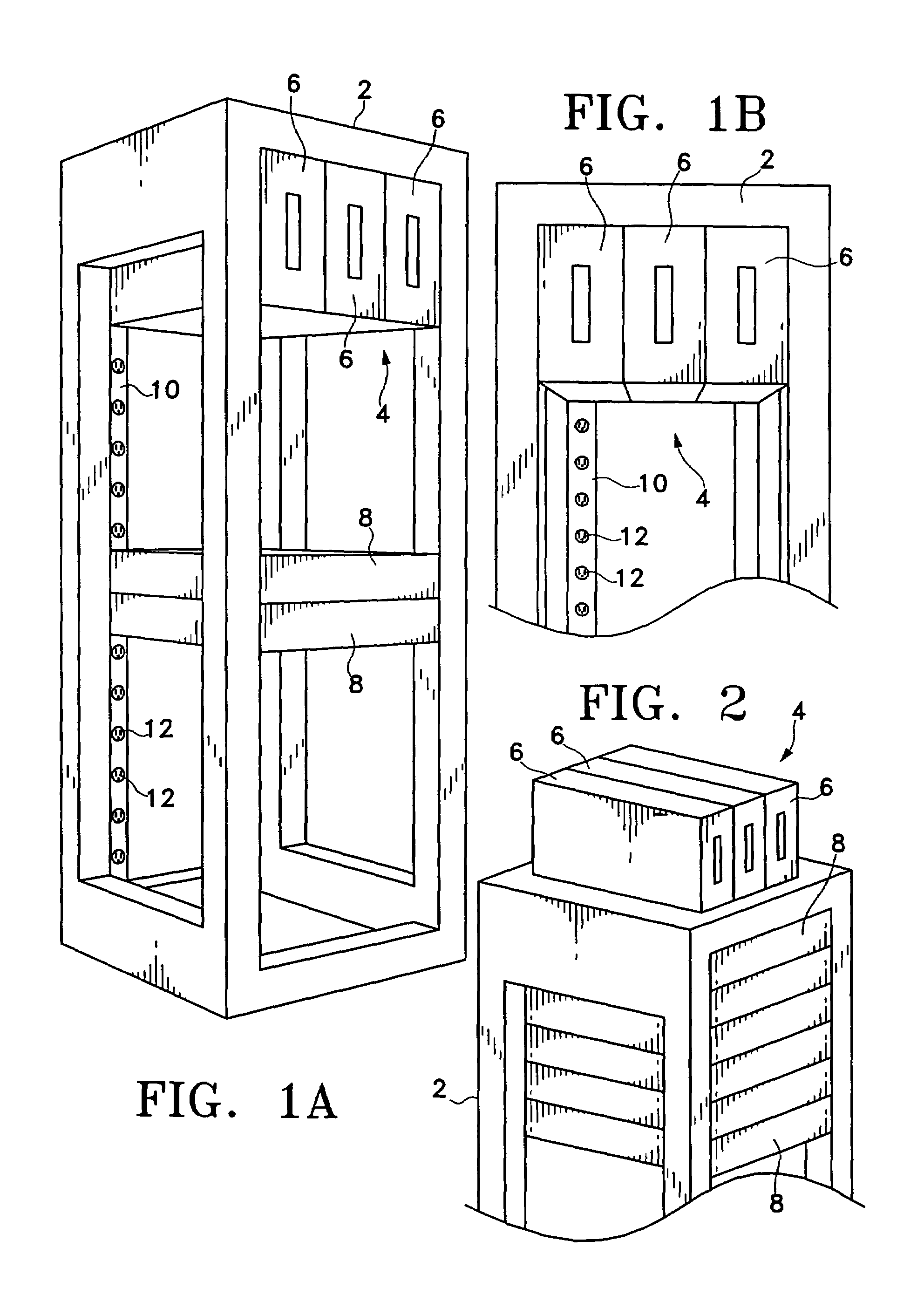
[0043]Before describing the present invention, it is to be understood that unless otherwise indicated this invention need not be limited to applications for housing and operating servers, as such may vary. Server farms and server racks are used here as examples. It is understood that some variations of the invention may be applied to other applications where large numbers of operating computers or data storage arrays are placed in close proximity of each other (e.g. telecommunication centers, where a large number of network computer are place in the same room for routing phone calls or mange data transfer).

[0044]A computer rack is used herein as an exemplary application to illustrate the functionality of the different aspects of the invention disclosed herein. It will be understood that certain variations of the present invention may be applied in a variety of applications for housing and / or operating a large number of electronic devices or systems in close proximity of each other.

[...


PUM


Abstract

The invention relates to a computer rack, frame or system having a direct current power supply positioned at the upper portion of the rack. In one variation, the DC power supply is placed in the highest shelf in the computer rack. In another variation, the DC power supply is placed on top of the computer rack. In yet another variation, a dual column computer rack with a back-to-back configuration is implemented with DC power supplies placed in a top shelf of the one of the computer columns. The DC power supply may comprise of one or more direct current power supply modules configured to provide fail over protection. In another aspect of the invention, the power supply modules are placed in a separate rack and provide direct current to support computers in one or more computer racks.

Description

CROSS-REFERENCE TO RELATED APPLICATIONS[0001]This application is claiming the benefit of priority to U.S. provisional application Ser. No. 60 / 471,430 entitled “COMPUTER RACK WITH POWER DISTRIBUTION SYSTEM” filed May 16, 2003, which is incorporated herein by reference in its entirety.FIELD OF THE INVENTION[0002]This invention relates to the manner in which computers are configured and provided in a given area in order to conserve space and deal with cooling issues associated with housing a large number of computers. Aspects of the invention assist with increasing the density at which computers may be provided, particularly in a network server or host environment. In particular, a power supply unit for supporting the electrical needs of the various computers in a computer rack may be utilized to improve heat dissipation of a multi-computer system house in the computer rack.BACKGROUND OF THE INVENTION[0003]As information technology has rapidly progressed in the past ten years, the role...

Claims


Application Information

Patent Timeline
IPC IPC(8): H05K7/20H01R12/16G06F1/18
CPCH05K7/1492G06F1/189
Inventor COGLITORE, GIOVANNI
Owner HEWLETT-PACKARD ENTERPRISE DEV LP
Why Eureka
Try Eureka