
Heat exchanger

Inactive Publication Date: 2007-01-16
FUJIKOSHI MACHINERY
View PDF8 Cites 0 Cited by
  • Summary
  • Abstract
  • Description
  • Claims
  • Application Information

AI Technical Summary

Benefits of technology

[0013]An object of the present invention is to provide a heat exchanger which includes a heat exchanging tube whose heat conductivity is greater than that of the conventional fluororesin tube and from which no metal ions are solved out, and which is capable of easily adjusting temperature of a machining liquid, e.g., slurry, etching liquid.
[0015]Then, the inventors found that the heat exchanging tube made of the ceramic, which is made by baking silicon carbide (SiC), can be effectively used.
[0018]The heat exchanger may further comprise inlets and outlets of the machining liquid and a liquid for adjusting temperature, and the inlets and outlets make the machining liquid and the liquid for adjusting the temperature flow as countercurrents. With this structure, the temperature of the machining liquid can be easily adjusted.
[0020]Therefore, heat exchange between the machining liquid and the temperature-adjusting liquid can be rapidly executed, and the temperature of the machining liquid can be easily adjusted.
[0021]Unlike the conventional heat exchanger including the fluororesin heat exchanging tube, the heat conductive area of the ceramic heat exchanging tube can be small and the size of the heat exchanger can be small. Therefore, the residence time of the machining liquid in the heat exchanger of the present invention can be shorter, and the temperature of the machining liquid can be precisely adjusted. Further, the rate of abrading or cutting work pieces can be easily controlled, and flatness of abraded faces or cut faces of the work pieces can be improved.

Problems solved by technology

If the temperature of the etching liquid is high, the etching function is sharply increased, so it is difficult to control the etching rate.
However, heat conductivity of the heat exchanging tube 100 made of a fluororesin is low.
However, metal ions solved out from the stainless tube stick onto the surface of the silicon wafer 16 to be abraded so that the function of the semiconductor chips is adversely affected.

Method used


Image

  • Heat exchanger
  • Heat exchanger
  • Heat exchanger

Examples


Embodiment Construction

[0028]Preferred embodiments of the present invention will now be described in detail with reference to the accompanying drawings.

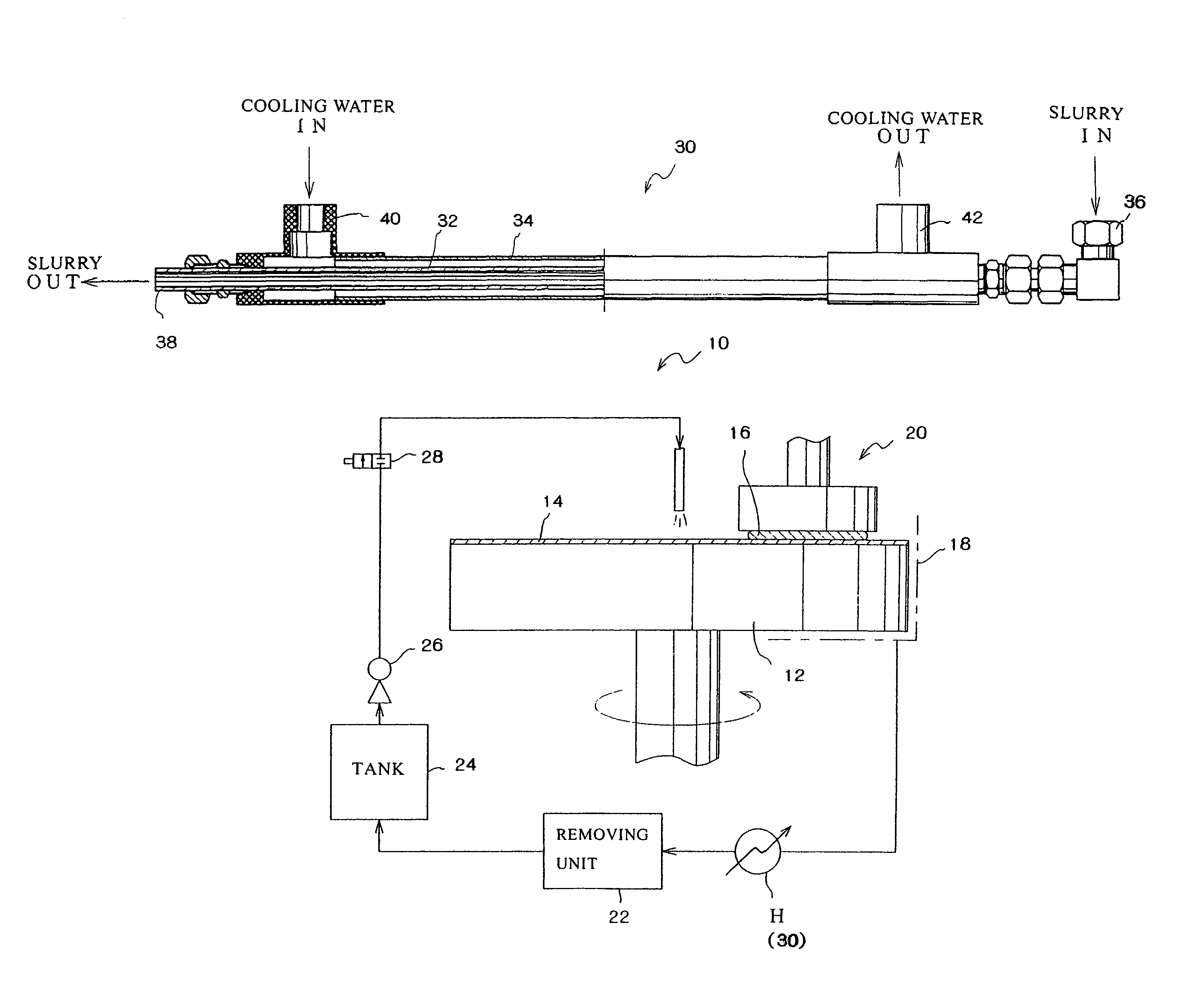
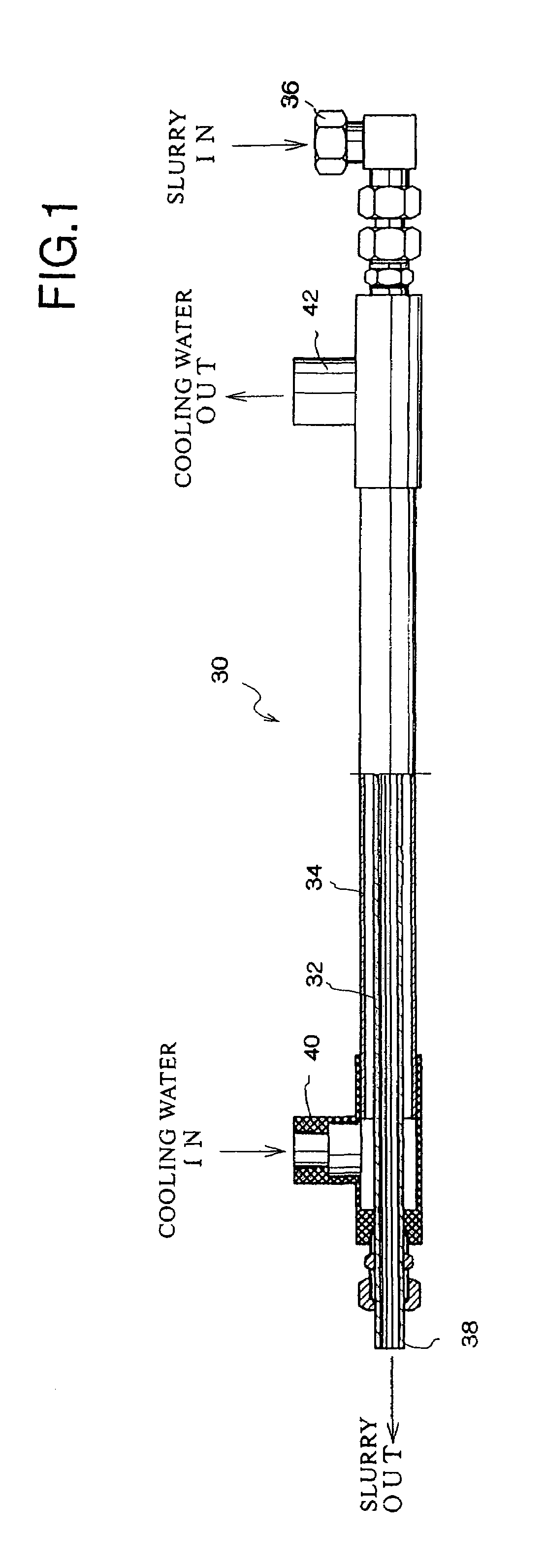
[0029]An embodiment of the heat exchanger of the present invention is shown in FIG. 1. The heat exchanger 30 shown in FIG. 1 has a double-tube structure. Namely, the heat exchanger 30 includes: an inner ceramic heat exchanging tube 32 in which slurry including abrasive grains flows; and an outer tube 34 which covers the inner heat exchanging tube 32 and in which cooling water (the temperature-adjusting liquid) flows along an outer circumferential face of the inner heat exchanging tube 32. The inner heat exchanging tube 32 is made of a ceramic made by baking silicon carbide (SiC) and the outer tube 34 is made of vinyl chloride or fluororesin. The slurry, which is an example of machining liquid and which flows in the heat exchanging tube 32, and the cooling water, which flows in a flow path formed between an inner circumferential face of the outer tube 34 an...


PUM

PropertyMeasurementUnit
Temperatureaaaaaaaaaa

Abstract

A method for adjusting temperature of a machining liquid, e.g., slurry, etching liquid, by passing the machining liquid through a heat exchanger. The heat exchanger, which adjusts the temperature of the machining liquid, includes a ceramic heat exchanging tube which is made by baking silicon carbide (SiC).

Description

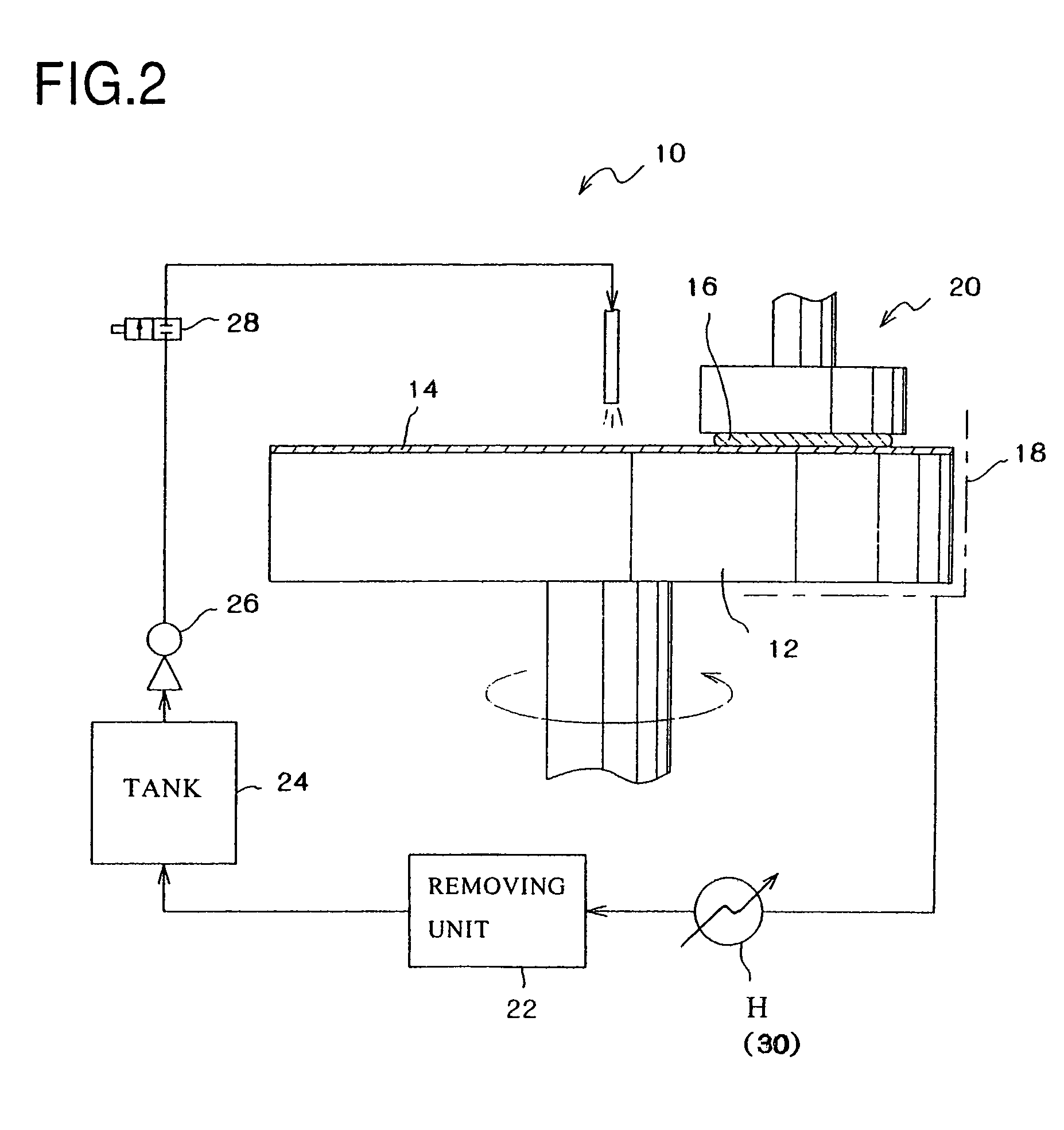
CROSS-REFERENCE TO RELATED APPLICATION[0001]This application is a continuation of U.S. patent application Ser. No. 10 / 007,820 filed Dec. 5, 2001, now abandoned, the specification of which is incorporated by reference herein.FIELD OF THE INVENTION[0002]The present invention relates to a heat exchanger, and more precisely to a heat exchanger capable of adjusting temperature of a machining liquid, e.g., slurry of abrading or cutting work pieces.BACKGROUND OF THE INVENTION[0003]In the case of abrading silicon wafers, the silicon wafers are abraded by, for example, an abrasive machine 10 shown in FIG. 2. In the abrasive machine 10, abrasive cloth 14 is adhered on a rotating abrasive plate 12. A silicon wafer 16 is pressed onto the abrasive cloth 14 by an abrasive head 20 so that a surface of the silicon wafer 16 can be abraded. Slurry including abrasive grains is supplied to the surface of the silicon wafer 16, and the used slurry is collected to be reused.[0004]Namely, the slurry, in wh...

Claims


Application Information

Patent Timeline
IPC IPC(8): F28D7/10B21D53/02B24B37/015B24B57/02F28F21/04H01L21/304
CPCB24B57/02F28D7/106F28F21/04Y10T29/49361Y10T29/4935Y10T29/5176Y10S165/905
Inventor NAKAMURA, YOSHIOOTSUKA, YOSHIO
Owner FUJIKOSHI MACHINERY
Learn More