
Method for improving multipath mitigator low path separation error behavior

Inactive Publication Date: 2006-12-21
FISHER JONATHAN D
View PDF1 Cites 6 Cited by
  • Summary
  • Abstract
  • Description
  • Claims
  • Application Information

AI Technical Summary

Benefits of technology

[0014] c. Yet a further objective of the invention is to avoid degrading multipath mitigation error behavior obtained when those results are optimal or near optimal as in the high path separation regime of operation.

Problems solved by technology

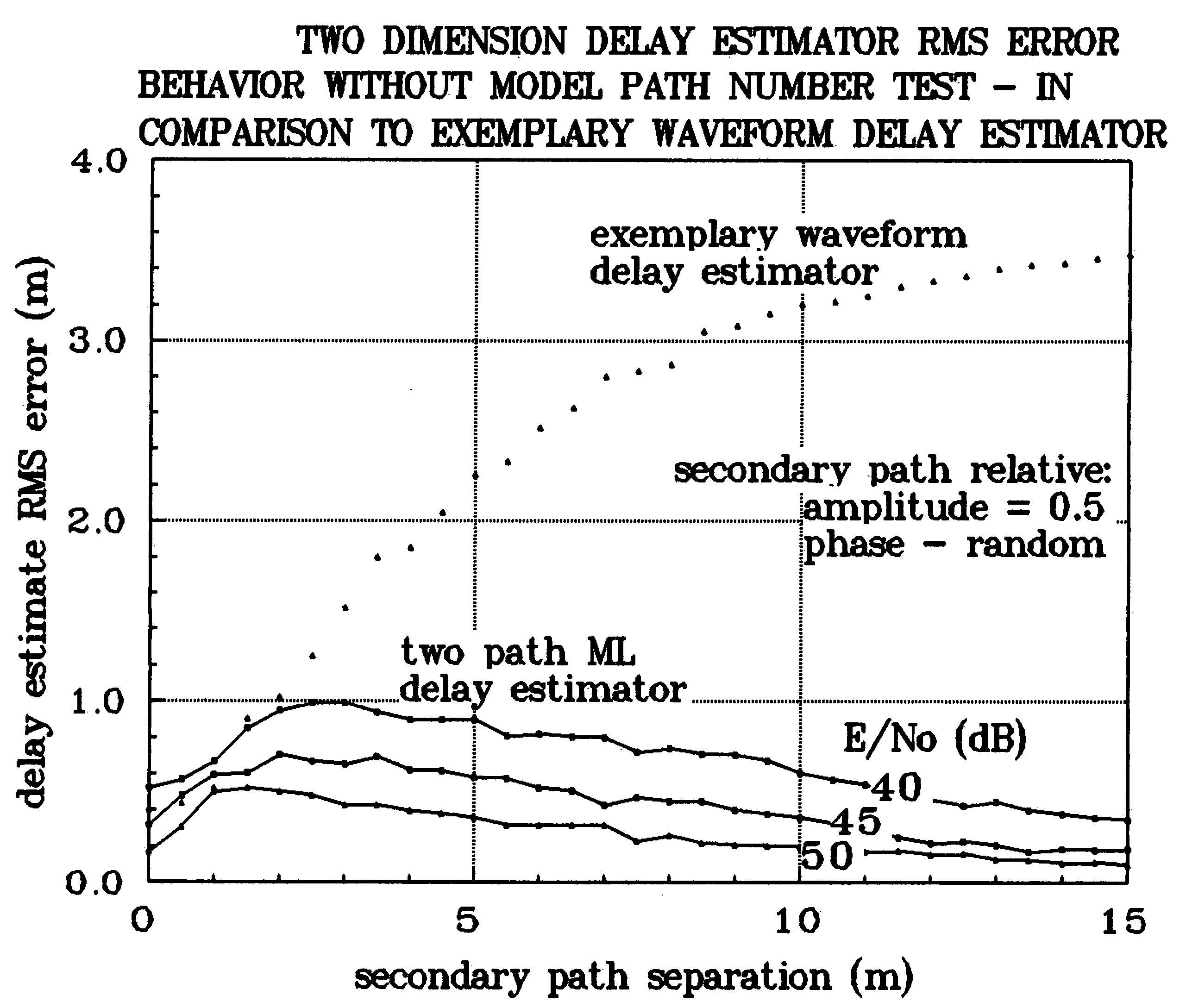
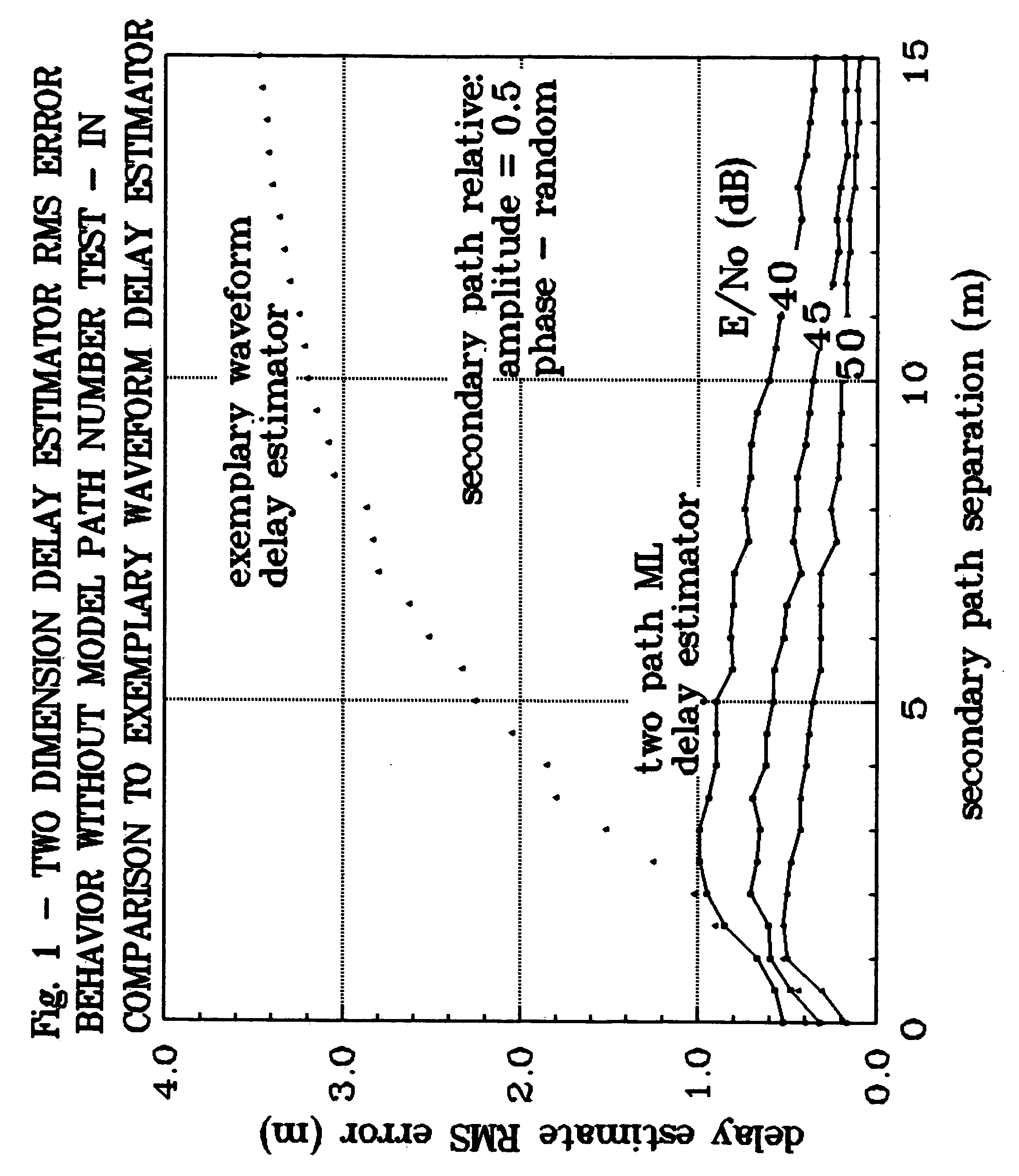
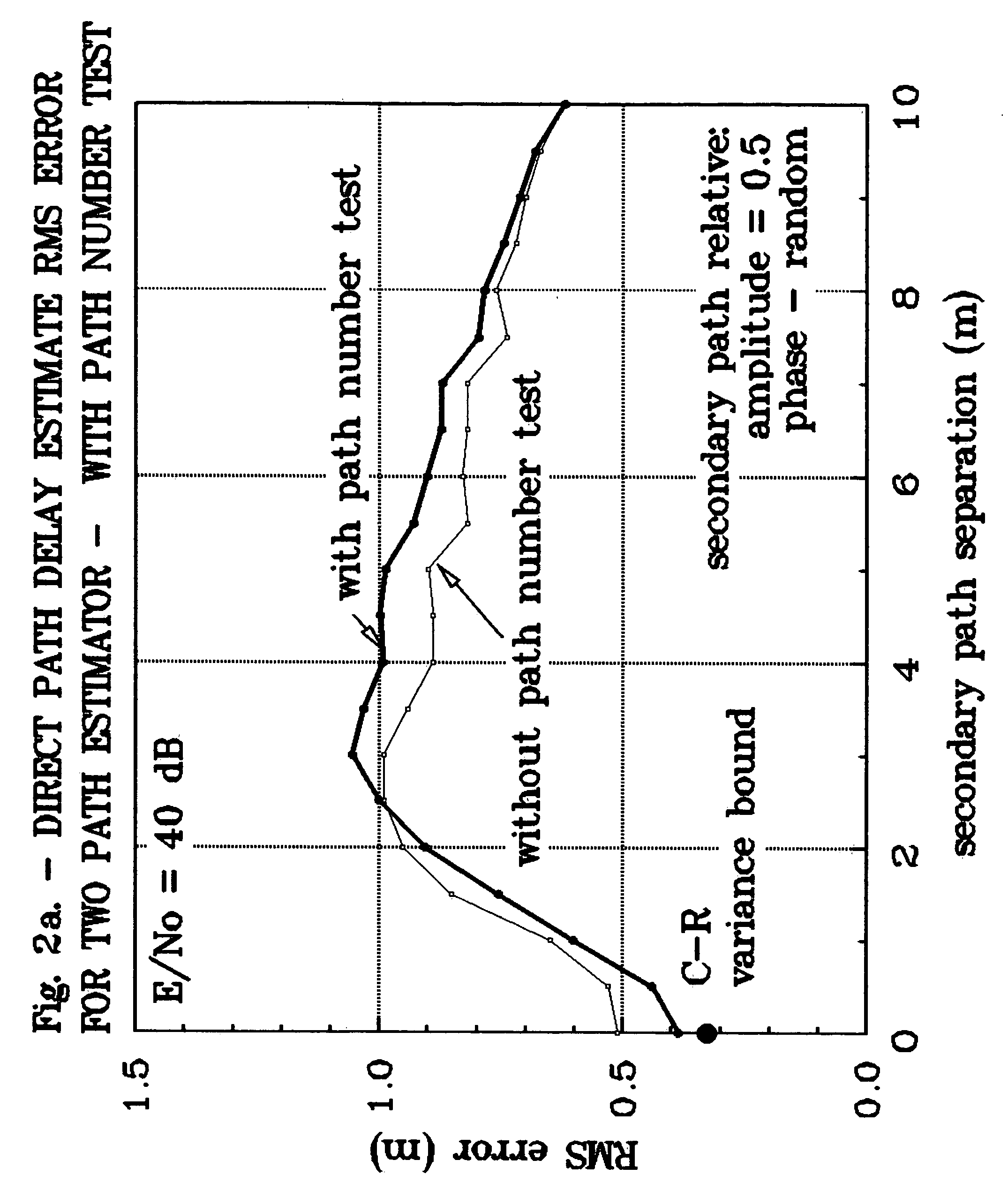
When using either ML method there exist effects at low path separation that may preclude obtaining the best possible results considering all possible estimators.
But if only a single path signal is observed then the two-path ML estimator is sub-optimal and will produce estimation results inferior to what otherwise might be obtained.
When low path separation applies there is ambiguity (ill-conditioning) in the signal model.
If a two-path signal, as an example, is observed then, where secondary path separation is small, the ambiguity gives rise to larger pseudorange errors than would be obtained with a single-path estimator.
In effect, the ambiguity creates uncertainty in deciding which model best applies from the point of view of least ranging error.

Method used


Image

  • Method for improving multipath mitigator low path separation error behavior
  • Method for improving multipath mitigator low path separation error behavior
  • Method for improving multipath mitigator low path separation error behavior

Examples


Embodiment Construction

Signal Receivers

[0019] In the ranging systems' signal receivers contemplated here the received RF (radio frequency or sonic or light frequency) signal is most commonly translated to base-band to obtain a signal with no carrier component. This is done in the interest of minimizing the signal sampling rate needed to preserve the range bearing information carried by the signal envelope. At base-band the received signal r(t) can be written as a composite of the direct and secondary path signal components as r⁡(t)=∑i=1I⁢Ai⁢m⁡(t-τi)⁢ⅇjϑi+n⁡(t);t0≤t≤t0+T0,(1)

where Ai denotes the amplitude of the ith=1, . . . , I signal component of the composite received signal, m(t) denotes the signal modulation which is common to all signal components, τi denotes the delay of the ith=1, . . . , I signal component, φi denotes the carrier phase of the ith=1, . . . ,I signal component, generally considered randomly varying over [0, 2π], and T0 denotes the duration of signal observation. In eq. (1) the v...


PUM


Abstract

In signal transmission ranging systems such as GPS, radar, and the like, accuracy of the ranging information most generally is effected by the presence of multiple paths of signal transmission, i.e., multipath. Optimal methods for estimating signal delay are signal model dependent. Signal models are most ambiguous with secondary path signals near the delay of the direct path signal. This invention provides a means of discriminating between received signals in which no secondary path signals are present in the signal observations and where one or more secondary path signals are present in those observations, and the number of such secondary path signals. Means described in the invention to accomplish this discrimination are based on Maximum Likelihood (ML) signal parameter estimation processes; processes which are model dependent. The invention provides the mechanism to identify the model appropriate to the observed signal. It accomplishes this by comparing the residual for an ith order ML estimator, where order refers to the number of signal paths for which the estimator is optimal, to a discriminant determined either analytically or empirically and deciding on i distinct signals are present in the observation of signal if for all (i-k)th order estimators, for k<i−1, the residual is greater than the discriminant for that order estimator and the residual of the ith order estimator is not greater than the discriminant for that order estimator.

Description

BACKGROUND OF THE INVENTION [0001] 1. Field of the Invention [0002] This invention relates to signal transmission ranging systems, such as GPS, radar, sonar, lidar and the like, in which the generally deleterious multiple propagation path (multipath) induced ranging errors are operating. More specifically, this invention provides improvement in ranging error when secondary path signals are not far separated from the direct path signal. [0003] 2. Description of Related Art [0004] The direct and each secondary path signal propagated to a signal receiver can be described by three parameters: amplitude, carrier phase, and signal modulation delay. Secondary path signals most generally result from reflections of direct path signals. Reflections are subject to additional propagation loss, delay, and electromagnetic effects (phase shift) characteristic of the reflecting materials. In toto, relative to the direct path signal, reflected signals are observed later in time with generally lower ...

Claims


Application Information

Patent Timeline
IPC IPC(8): H04L27/00
CPCG01S7/292H04L25/03006G01S19/22
Inventor FISHER, BENJAMINWEILL, LAWRENCE
Owner FISHER JONATHAN D
Learn More