
Method and apparatus for downlink joint detection in a communication system

Inactive Publication Date: 2007-01-09
L 3 COMM CORP +1
View PDF4 Cites 8 Cited by
  • Summary
  • Abstract
  • Description
  • Claims
  • Application Information

AI Technical Summary

Benefits of technology

[0066]It is, therefore, an object of the present invention to provide an apparatus and method for reducing implementation complexity of a ZF joint detector used for a downlink receiver in a CDMA communication system.
[0067]It is another object of the present invention to provide an apparatus and method for calculating a low initial complexity value of a ZF joint detector used for a downlink receiver in a CDMA communication system.

Problems solved by technology

Therefore, a signal from a user at a long distance undergoes interference with a signal from a user at a short distance, so the system using the matched filter cannot correctly restore user signals.
An optimal joint detector, such as an ML (Maximum Likelihood) joint detector using an ML algorithm, has high complexity, so it is not possible to realize the ML joint detector at the current state of the art.
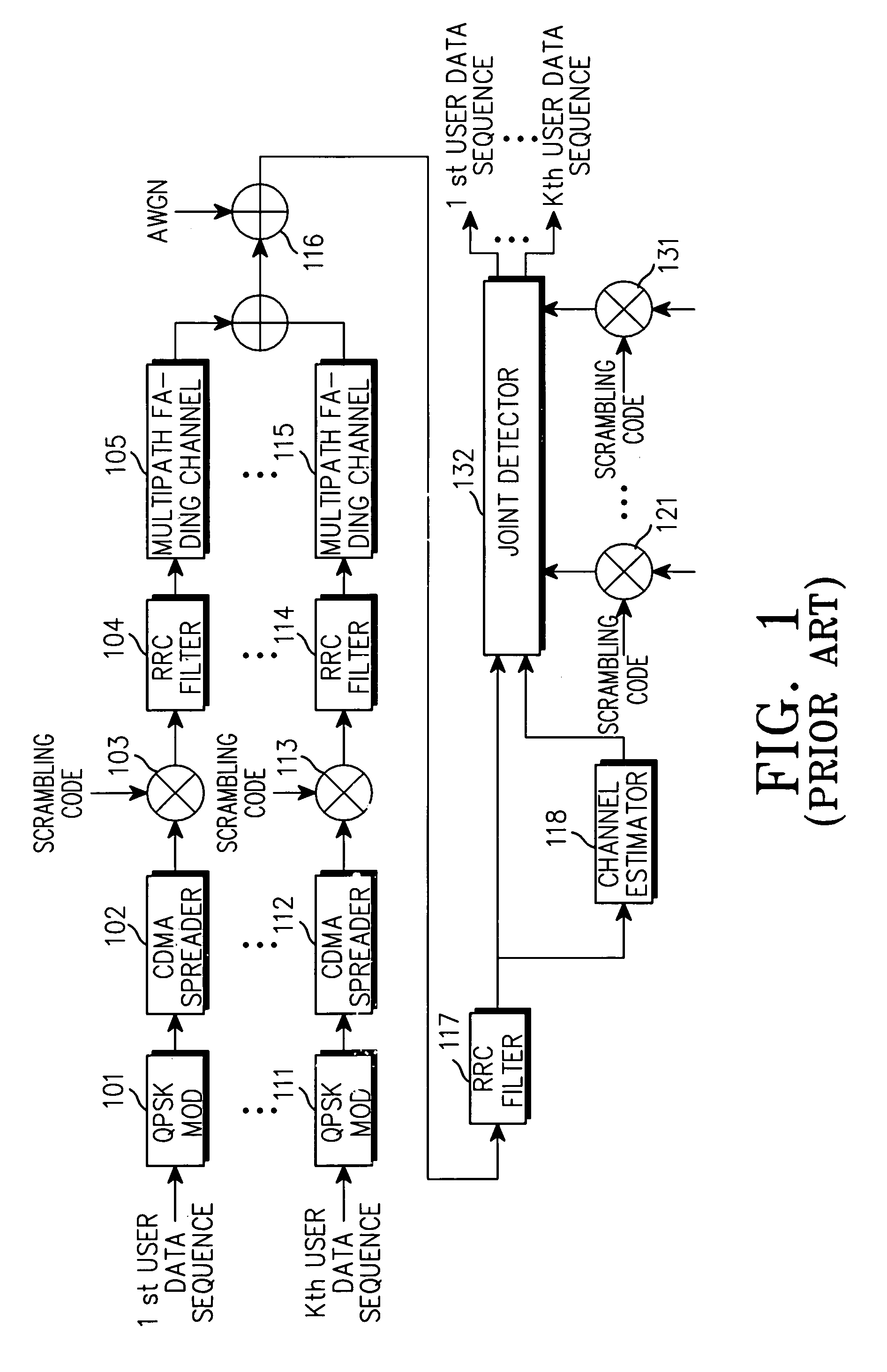
The symbol-level ZF joint detector is simpler in complexity than the optimal joint detector, but it still has a high complexity and requires accurate channel estimation and many calculations.
Therefore, an increase in the length of the data sequence or an increase in the number of users causes a considerable increase in calculations of the A matrix and the inverse matrix so that the joint detector cannot be realized.
Here, calculations of the symbol-level ZF joint detector will be expressed in terms of the number of multiplications that cause an increase in complexity in actual implementation.
However, the chip-level ZF joint detector requires calculations of the same order for N, Q and W, so it still requires considerably high complexity.
Accordingly, it is not possible to reduce the calculations and complexity to a desirable level, causing a problem in realization.

Method used


Image

  • Method and apparatus for downlink joint detection in a communication system
  • Method and apparatus for downlink joint detection in a communication system
  • Method and apparatus for downlink joint detection in a communication system

Examples


Embodiment Construction

[0074]A preferred embodiment of the present invention will be described herein below with reference to the accompanying drawings. In the following description, well-known functions or constructions are not described in detail since they would obscure the invention in unnecessary detail.

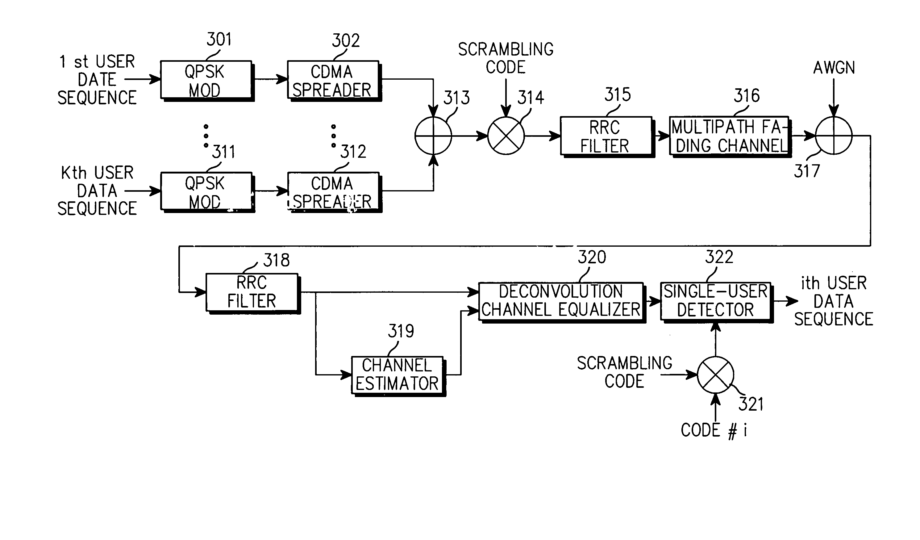
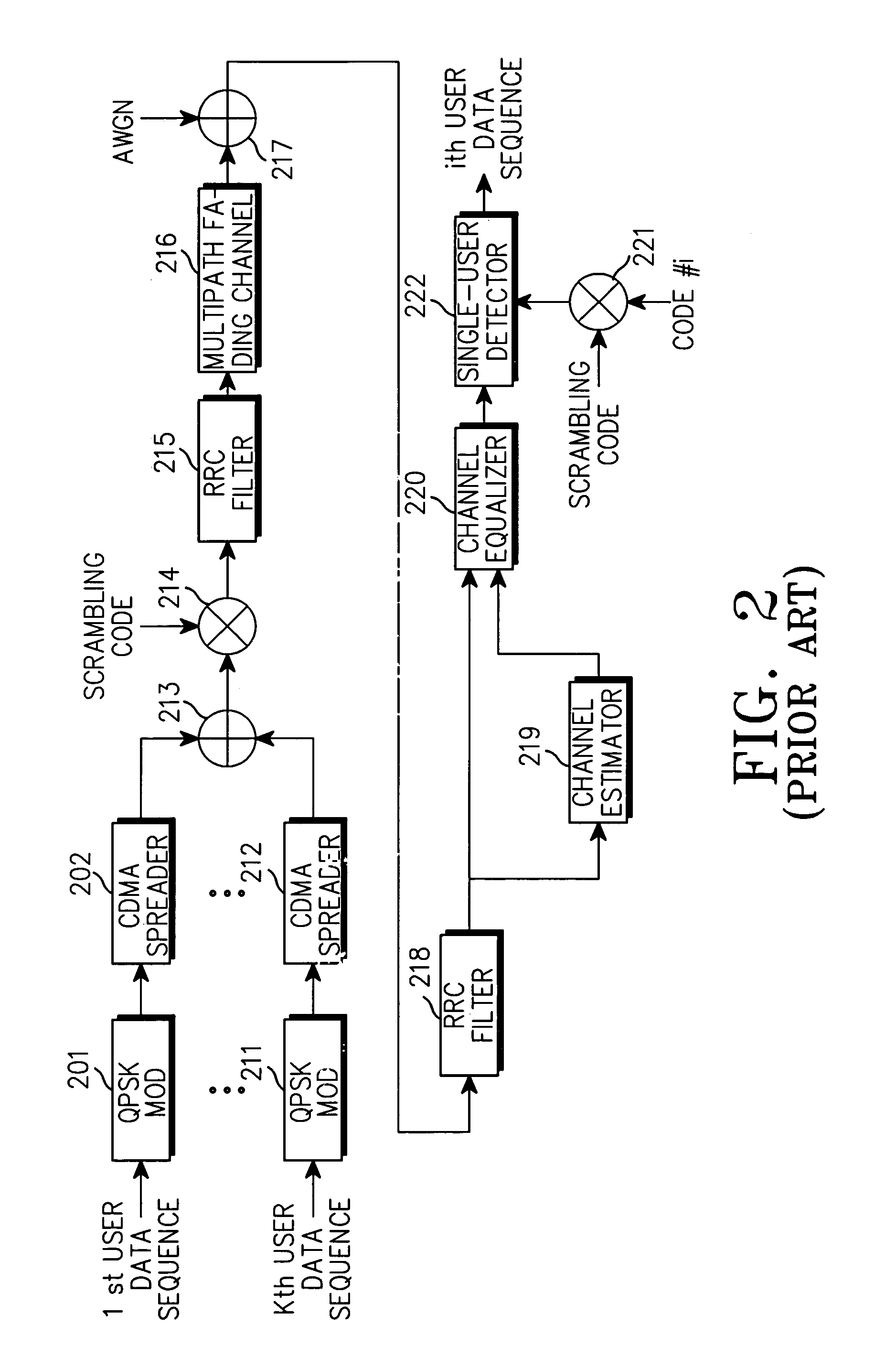
[0075]FIG. 3 illustrates structures of a downlink transmitter, a channel and a receiver with a joint detector in a 3GPP / TDD CDMA communication system according to an embodiment of the present invention. Here, in the downlink, a transmitter serves as a base station and a receiver serves as a mobile station. Further, the transmitter has the same structure as the transmitter illustrated in FIG. 2.

[0076]Referring to FIG. 3, a first user's data sequence is modulated into a QPSK signal by a QPSK modulator 301, and then spread with a spreading code assigned to the first user by a CDMA spreader 302. Likewise, a Kth user's data sequence is modulated into a QPSK signal by a QPSK modulator 311, and then spread w...


PUM


Abstract

A ZF joint detection apparatus for a downlink receiver, the apparatus comprising: a channel estimator for estimating a channel impulse response of a multipath fading channel of a received signal; a channel equalizer for estimating a transmission signal by performing channel compensation and removing multipath interference by a deconvolution technique based on the estimated channel impulse response; and a user detector for detecting a symbol-level data sequence transmitted by a specific user by despreading the transmission signal estimated by the channel equalizer with a spreading code for the specific user and a scrambling code.

Description

PRIORITY[0001]This application claims priority to an application entitled “Method and Apparatus for Downlink Joint Detection in a Communication System” filed in the Korean Industrial Property Office on Jun. 1, 2001 and assigned Ser. No. 2001-30676, the contents of which are hereby incorporated by reference.BACKGROUND OF THE INVENTION[0002]1. Field of the Invention[0003]The present invention relates generally to a communication system, and in particular, to a joint detection apparatus and method used for a downlink receiver in a CDMA (Code Division Multiple Access) communication system.[0004]2. Description of the Related Art[0005]A CDMA communication system simultaneously receives / transmits a plurality of user signals in the same frequency band and time period, after separating the user signals with associated spreading codes previously assigned to the respective users. A radio channel undergoes an attenuation of waves and a change in fading according to circumstances. A transmission...

Claims


Application Information

Patent Timeline
IPC IPC(8): H04B1/707H04B1/69H04L25/02H04L25/03
CPCH04L25/0216H04L25/03012H04L25/0242H04L2025/03624H04B1/711
Inventor HUH, HOONKANG, HEE-WONPENG, WEI-CHUNGLAI, DENNISCHEN, JENG-HONG
Owner L 3 COMM CORP
Learn More