Dielectric antenna and radio device using the same
a radio device and dielectric technology, applied in the field of dielectric antennas, can solve the problems of large and heavy dielectric antennas, difficult operation to evenly fill the inside of the waveguide with dielectrics, and high machining costs of conventional dielectric antennas, so as to achieve small and inexpensive dielectric antennas, stable operation, and constant impedance and wavelength inside the dielectric waveguide
- Summary
- Abstract
- Description
- Claims
- Application Information
AI Technical Summary
Benefits of technology
Problems solved by technology
Method used
Image
Examples
first embodiment
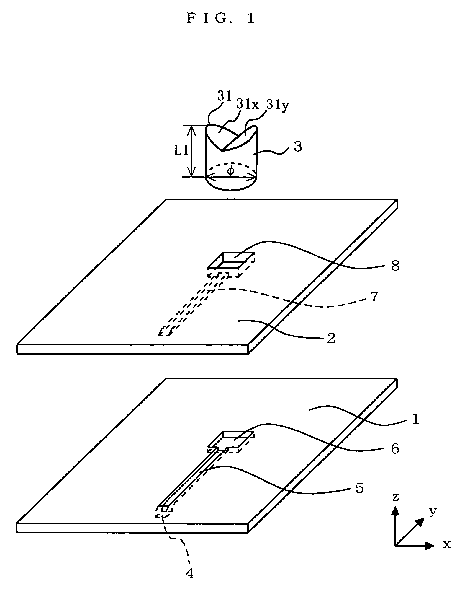
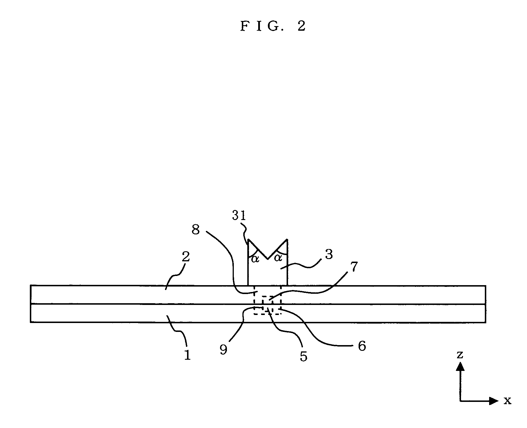
[0118]FIG. 1 is an exploded perspective view illustrating a dielectric antenna according to the first embodiment of the present invention. FIG. 2 is a front view of the dielectric antenna illustrated in FIG. 1. In these and subsequent figures, it is assumed that the xz plane represents the electric field plane, and the yz plane represents the magnetic field plane. Referring to FIG. 1 and FIG. 2, the dielectric antenna includes a lower conductor plate 1, an upper conductor plate 2 and a loading dielectric block 3.
[0119]The loading dielectric block 3 is made of a dielectric material such as polypropylene. A notch 31 is formed in an upper portion of the loading dielectric block 3. The notch 31 is formed by cutting off an upper portion of a cylindrical dielectric with an edged tool, or the like. The notch 31 is formed by cutting the cylindrical dielectric from two opposite points along the circumference of the upper surface of the cylindrical dielectric in an inclined downward direction...
second embodiment
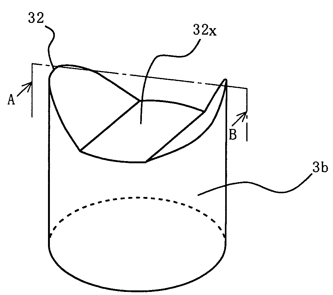
[0138]The second embodiment of the present invention differs from the first embodiment only in the shape of the loading dielectric block. Otherwise, the dielectric antenna of the second embodiment is as illustrated in FIG. 1. Therefore, only the shape of the loading dielectric will be discussed below. FIG. 9 is a perspective view illustrating a loading dielectric block used in the dielectric antenna according to the second embodiment of the present invention. FIG. 10 is a vertical cross-sectional view of the loading dielectric block of FIG. 9 taken along line A-B.
[0139]Referring to FIG. 9 and FIG. 10, a depressed portion 32 is formed in an upper portion of a loading dielectric block 3b. The depressed portion 32 is formed by cutting off an upper portion of a cylindrical dielectric with an edged tool, or the like. The depressed portion 32 is formed by cutting the cylindrical dielectric from two opposite points along the circumference of the upper surface of the cylindrical dielectric ...
third embodiment
[0144]FIG. 12 is an exploded perspective view illustrating a dielectric antenna according to the third embodiment of the present invention. In FIG. 12, elements that are functionally the same as those of the first embodiment will be denoted by the same reference numerals and will not be further described below. The third embodiment uses, as the loading dielectric, a loading dielectric block 3d having a depressed portion 34 whose upper portion has a truncated cone shape. The loading dielectric block 3d has the depressed portion 34, whereby the upper portion thereof is in a bowl shape, and the depressed portion 34 includes, at the bottom thereof, a flat (horizontal) surface portion 34a parallel to the bottom surface of the loading dielectric block 3d. FIG. 13 is an enlarged perspective view of the loading dielectric block 3d.
[0145]Thus, with the loading dielectric block 3d with the bowl-shaped upper portion, an omni directional slope is formed toward the periphery with a flat bottom ...
PUM
 Abstract
Description
Claims
Application Information
 - Generate Ideas
- Intellectual Property
- Life Sciences
- Materials
- Tech Scout
- Unparalleled Data Quality
- Higher Quality Content
- 60% Fewer Hallucinations
Browse by: Latest US Patents, China's latest patents, Technical Efficacy Thesaurus, Application Domain, Technology Topic, Popular Technical Reports.
© 2025 PatSnap. All rights reserved.Legal|Privacy policy|Modern Slavery Act Transparency Statement|Sitemap|About US| Contact US: help@patsnap.com


