
Magnetic toner

a toner and magnetic technology, applied in the field of magnetic toner, can solve the problems of difficult to uniformly disperse toner, reddish tint of magnetic material, various problems, etc., and achieve the effect of avoiding contamination of developing sleeves, stable image density, and superior low-temperature fixing performan

Active Publication Date: 2007-01-09
CANON KK
View PDF13 Cites 28 Cited by
  • Summary
  • Abstract
  • Description
  • Claims
  • Application Information

AI Technical Summary

Benefits of technology

[0012]An object of the present invention is to provide a toner having solved the problems discussed above, and to provide a magnetic toner which can attain a stable image density without dependence on environment.
[0013]Another object of the present invention is to provide a magnetic toner which enables formation of high-grade images over a long period of time without causing scratches of latent image bearing members.
[0014]Still another object of the present invention is to provide a magnetic toner having a high coloring power and promising less toner consumption.
[0017]According to the present invention, the magnetic material with small particle diameter is improved in uniform dispersibility in the resin, so that stable image density can be attained and high-grade images can be formed over a long period of time. Also, according to the present invention, internal additives can stand well dispersed even in toners made to have small particle diameter, and a toner can be obtained which has superior low-temperature fixing performance and may cause no contamination of developing sleeves and fixing rollers even in long-term running.

Problems solved by technology

However, when made small in particle diameter, the magnetic material comes apt to have a reddish tint and also comes very difficult to disperse uniformly in the toner.
Hence, this tends to cause various problems.
For example, where toners are made to have small particle diameter in order to improve dot reproducibility in digital machines or the like, a toner containing the magnetic material in a large quantity may accumulate on a toner carrying member (developing sleeve) if the magnetic material stands dispersed insufficiently, image density may lower and the non-uniformity of tone that is called sleeve ghost may occur.
Problems may also arise such that the magnetic material tends to come off because of rubbing friction between toner particles themselves or between toner particles and a toner layer thickness control member, and that the magnetic material having come off scratches the photosensitive member (latent image bearing member) to cause defective images.
However, the adhesion between the binder resin and the magnetic iron oxide which constitute the magnetic toner is insufficient.
However, this measure is still unsatisfactory when the toner is made small in particle diameter or when the magnetic material with small particle diameter is used.

Method used


Image

  • Magnetic toner
  • Magnetic toner
  • Magnetic toner

Examples


production example 1-1

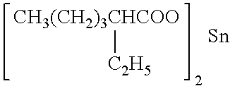
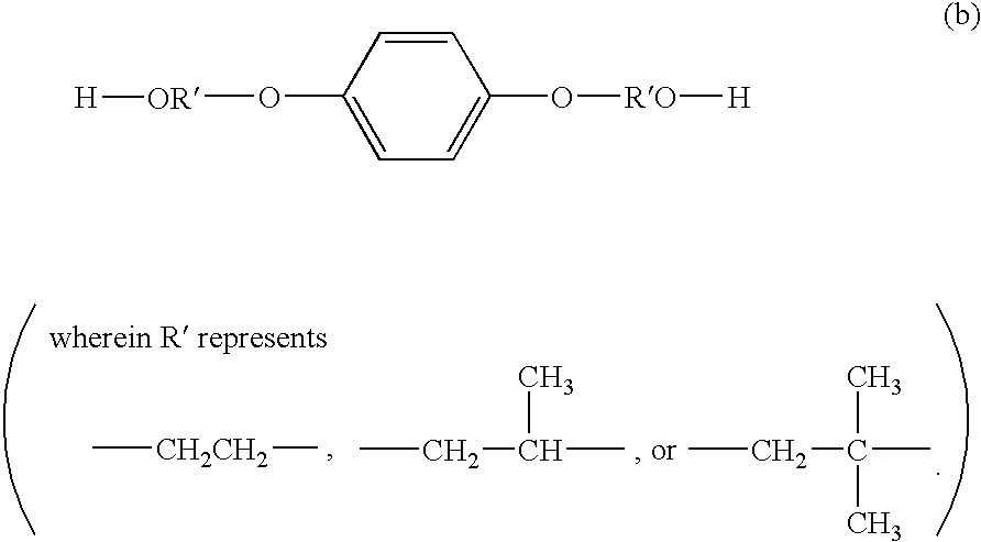
[0146]Monomers for obtaining polyester and an alkylcarboxylic acid tin compound as a catalyst were introduced into a four-necked flask, and a vacuum device, a water separator, a nitrogen gas feeder, a temperature measuring device and a stirrer were fitted thereto. Reaction was carried out in an atmosphere of nitrogen, heating to 230° C. After the reaction was completed, the reaction product was taken out of the flask, then cooled, and thereafter pulverized to obtain Binder Resin 1-1 with a softening point of 138° C. The types of monomers and tin compound used and the physical properties of the resin obtained are shown in Table 6.

[0147]Binder Resin

Production Examples 1-2 to 1-10

[0148]Binder Resins 1-2 to 1-10 were obtained in the same manner as in Binder Resin Production Example 1-1 except that the amount and type of the monomers and alkylcarboxylic acid tin compound were changed as shown in Table 6 and that the reaction was carried out while confirming softening points and the reac...

production example 1-11

[0150]Monomers for obtaining polyester and an alkylcarboxylic acid tin compound were introduced into a four-necked flask, and a vacuum device, a water separator, a nitrogen gas feeder, a temperature measuring device and a stirrer were fitted thereto. With stirring in an atmosphere of nitrogen at a temperature of 130° C., a mixture of vinyl monomers shown in Table 6 and a polymerization initiator (dicumyl peroxide) was dropwise added from a dropping funnel over a period of 4 hours. This was kept at 130° C. for 3 hours, and thereafter heated to 230° C. to carry out reaction. After the reaction was completed, the reaction product was taken out of the flask, and thereafter pulverized to obtain Binder Resin 1-11 with a softening point of 140° C., containing a polyester resin component, a vinyl polymer component and a hybrid resin. The types of monomers and tin compound used and the softening point and other physical properties of the resin obtained are shown in Table 6.

[0151]Binder Resin...

production examples 1 -

Production Examples 1-a to 1-h

[0154]Binder Resins 1-a to 1-h shown in Table 7 were obtained in the same manner as in Binder Resin Production Example 1-1 except that the type and amount of the monomers and alkylcarboxylic acid tin compound were changed as shown in Table 7.


PUM

PropertyMeasurementUnit
Lengthaaaaaaaaaa
Lengthaaaaaaaaaa
Massaaaaaaaaaa

Abstract

In a magnetic toner having toner particles containing at least a binder resin and a magnetic material, the binder resin is chiefly composed of a resin having a polyester unit synthesized using as a catalyst a tin compound represented by the following Formula (1), and the magnetic material has a number-average particle diameter of form 0.1 μm to 0.3 μm:(RCOO)2Sn  Formula (1)wherein R represents an alkyl group having 5 to 15 carbon atoms. This magnetic toner can attain a stable image density without dependence on environment and enables formation of high-grade images over a long period of time without causing scratches of latent image bearing members.

Description

BACKGROUND OF THE INVENTION[0001]1. Field of the Invention[0002]This invention relates to a magnetic toner used in a recording process such as electrophotography, electrostatic recording, electrostatic printing or toner jet recording.[0003]2. Related Background Art[0004]As methods for electrophotography, methods are conventionally known in which copied or printed images are obtained by forming an electrostatic latent image on a photosensitive member by utilizing a photoconductive material and by various means, subsequently developing the electrostatic latent image by the use of a toner to form a toner image, and transferring the toner image to a transfer medium such as paper as occasion calls, followed by fixing by the action of heat, pressure, heat-and-pressure, or solvent vapor.[0005]In a method of developing the electrostatic latent image, a magnetic one-component developing system making use of a magnetic toner is preferably used because it does not require any carrier and is ad...

Claims


Application Information

Patent Timeline
IPC IPC(8): G03G9/083C08G63/20C08G63/85G03G9/087G03G9/097
CPCC08G63/85G03G9/0833G03G9/0834G03G9/0836G03G9/09791G03G9/08755G03G9/08782G03G9/08793G03G9/08795G03G9/09783G03G9/0838C08G63/20B60R11/0235B60R2011/0017
Inventor DOJO, TADASHISHIBAYAMA, NENEMIZOO, YUICHIHASEGAWA, YUSUKE
Owner CANON KK
Learn More