Eureka AIR delivers breakthrough ideas for toughest innovation challenges, trusted by R&D personnel around the world.

Mixed mode microfluidic systems

a microfluidic system and mixed-mode technology, applied in the field of mixed-mode microfluidic systems, can solve the problems of limiting the operability of those systems, resulting in data that required more complex data deconvolution, etc., and achieve the effect of minimizing the excess hardware needed for fluid transpor

Active Publication Date: 2007-01-09
CAPLIPER LIFE SCI INC
View PDF112 Cites 148 Cited by
  • Summary
  • Abstract
  • Description
  • Claims
  • Application Information

AI Technical Summary

Benefits of technology

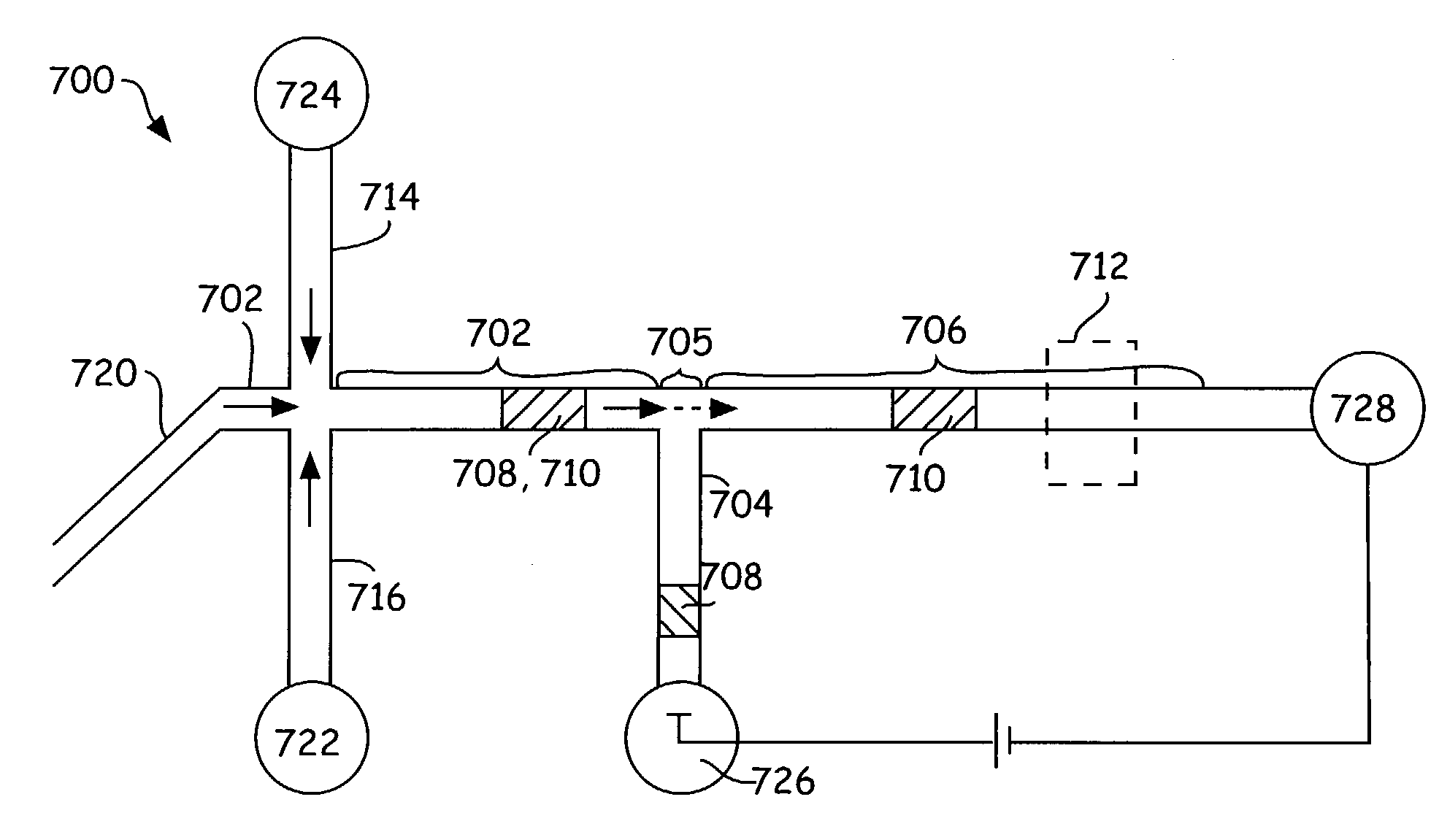
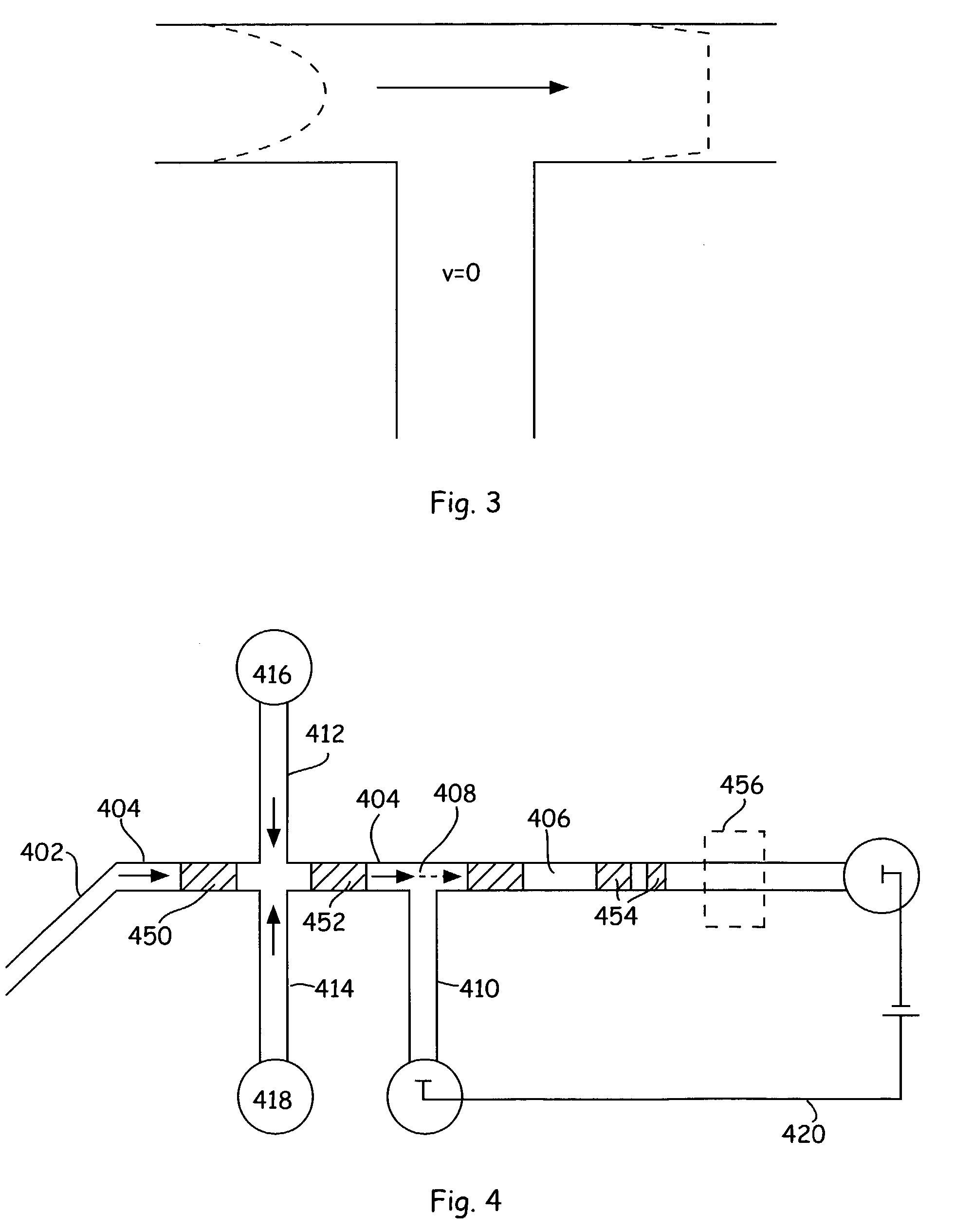
[0008]Other novel techniques, similar to selective ion extraction described above, are also described herein for separating and extracting analytes having different mobilities (e.g., different charge and / or mass), in which the microfluidic channel network is configured and dimensioned in such a way to proportion the fluidic driving forces to separate differently charged species in a fluidic sample by utilizing a reduced number of external pressure and voltage sources, e.g., by reducing the number of fluidic reservoirs needed for fluidic control to perform the separation as compared to previously described embodiments. In this way, excess hardware needed for fluid transport can be minimized and the microfluidic device can be operated with fewer fluidic reservoirs compared to previously described designs.

Problems solved by technology

While microfluidic systems have been delivering on their promises, the interconnected nature of microfluidic channel networks in the developed systems has led to some limitations of the operability of those systems.
However, the use of electric fields to drive material movement also drove electrophoretic separation or biasing of differentially charged species within the channels of the device, yielding data that required more complex data deconvolution.

Method used


Image

  • Mixed mode microfluidic systems
  • Mixed mode microfluidic systems
  • Mixed mode microfluidic systems

Examples


example 1

Separation of a Charged Species Using a Multiport Control System and a Off-Chip Assay Microfluidic Device

Reagents:

[0098]Enzyme: Protein Kinase A, a camp-dependent Protein Kinase, (Promega, Madison, Wis.)

[0099]Substrate: 5-FAM-LRRASLG_CONH1 of molecular weight 1129.5 d

[0100]Buffer: 5 mM MgCl2 (Sigma, St. Louis, Mo.), 0.01% Triton-X (Sigma), 1 mM DTT (Calbiochem), 10 μM ATP (Sigma), 2% DMSO (Burdick & Jackson, Muskegon, Mich.), in 100 mM HEPES buffer

Apparatus:

[0101]All experiments were performed either with a Caliper 100 development system or a Caliper 220 high-throughput screening system that were equipped with a multiport cartridge (Caliper Technologies Corp., Mountain View, Calif.). These systems are designed to provide a complete, integrated solution for primary assay screening. Each system includes automated sampling robotics, an arc-lamp or laser-based fluorescence detection system, and a complete software package for control and analysis. The chip mounts inside a cartridge, whi...


PUM

PropertyMeasurementUnit
hydrodynamic flow velocityaaaaaaaaaa
pressureaaaaaaaaaa
depthaaaaaaaaaa

Abstract

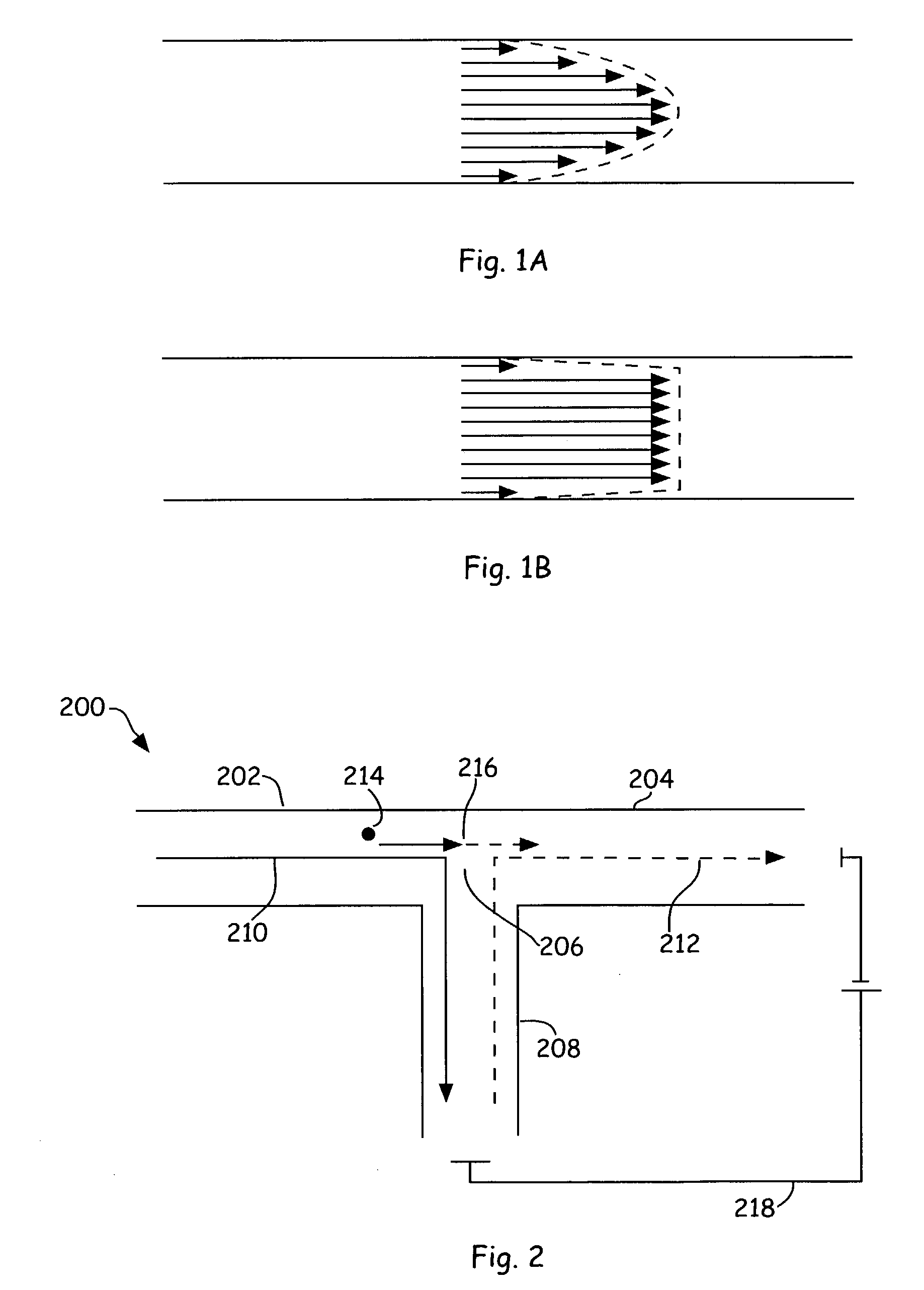
Methods and systems that employ hybrid fluid flow profiles for optimized movement of materials through channel networks. These systems employ hybrid pressure-based and electrokinetic based flow systems for moving materials through interconnected channel networks while maintaining interconnection among the various channel segments. In particular, the invention is generally directed to channel networks where flow in a first channel segment is driven by pressure flow with its consequent parabolic flow profile, while flow in an interconnected channel segment is dominated by electrokinetic flow with its consequent plug flow profile. The invention also provides channel networks wherein fluid flow in channel segments is driven by both pressure and electric field and the multiple species contained in a fluid plug are separated by altering the applied pressure and electric fields in the various channel segments of the channel networks.

Description

CROSS-REFERENCE TO RELATED APPLICATIONS[0001]This application claims the benefit of U.S. Provisional Application Nos. 60 / 361,957 filed Mar. 5, 2002 and 60 / 381,306 filed May 17, 2002, each of which is incorporated herein be reference in their entirety for all purposes.BACKGROUND OF THE INVENTION[0002]Microfluidic technology has been heralded as the next technological evolution in biological and chemical research, with its promise of faster, more accurate, readily automatable miniaturized experimentation. Many of the advantages of microfluidic experimentation are evident in the marketplace. For example, the Agilent 2100 Bioanalyzer and its menu of microfluidic devices and reagent kits, supplied by Caliper Life Sciences Inc., provide a versatile experimentation platform for performing a large number of different analyses important to life science researchers. The data produced by these systems is obtained rabidly in a digitized, highly reproducible fashion.[0003]High throughput experim...

Claims


Application Information

Patent Timeline
Patent Type & Authority Patents(United States)
IPC IPC(8): G01N27/447B01D57/02B01F13/00B01L3/00B03B13/00B03B13/04B03C5/00F04B19/00G01N37/00H02N11/00
CPCB01F13/0076B01L3/502746B01L3/502784H02N11/006F04B19/006G01N27/44791B01L2200/0673B01L2300/0816B01L2400/0415B01L2400/0487B01L2400/084B01L2300/0864B01F33/3031
Inventor CHIEN, RING-LINGPARCE, J. WALLACESPAID, MICHAEL
Owner CAPLIPER LIFE SCI INC
Why Eureka
Eureka Blog
Learn More