Fuel feed apparatus having conductive members grounded each other

a technology of conductive members and fuel feed, which is applied in the direction of machines/engines, filtration separation, separation processes, etc., can solve the problems of dielectric breakdown and cracks in sections

Active Publication Date: 2007-01-09
DENSO CORP
View PDF13 Cites 24 Cited by
  • Summary
  • Abstract
  • Description
  • Claims
  • Application Information

AI Technical Summary

Benefits of technology

[0008]In the present invention, a jet nozzle is made of conductive material to prevent a jet pump including the jet nozzle from charging. Therefore, the jet pump is avoided from causing dielectric breakdown due to increase of its charge amount. Accordingly, the jet pump is avoided from a cracking resulting from the dielectric breakdown. Additionally, the sub tank has a wide surface area, so that grounding can be performed freely. Therefore, the jet pump can be easily grounded via the sub tank.
[0010]A metallic joining member and a metallic forcing member can be easily grounded via a conductive mounting member and a conductive supporting member and the sub tank so as not to be charged.

Problems solved by technology

On the other hand, if a charge amount increases in the nonconductive member, the nonconductive members may cause dielectric breakdown.
Accordingly, it is likely that a crack may be caused from the section where the dielectric breakdown is caused.

Method used


Image

  • Fuel feed apparatus having conductive members grounded each other
  • Fuel feed apparatus having conductive members grounded each other
  • Fuel feed apparatus having conductive members grounded each other

Examples


first embodiment

(First Embodiment)

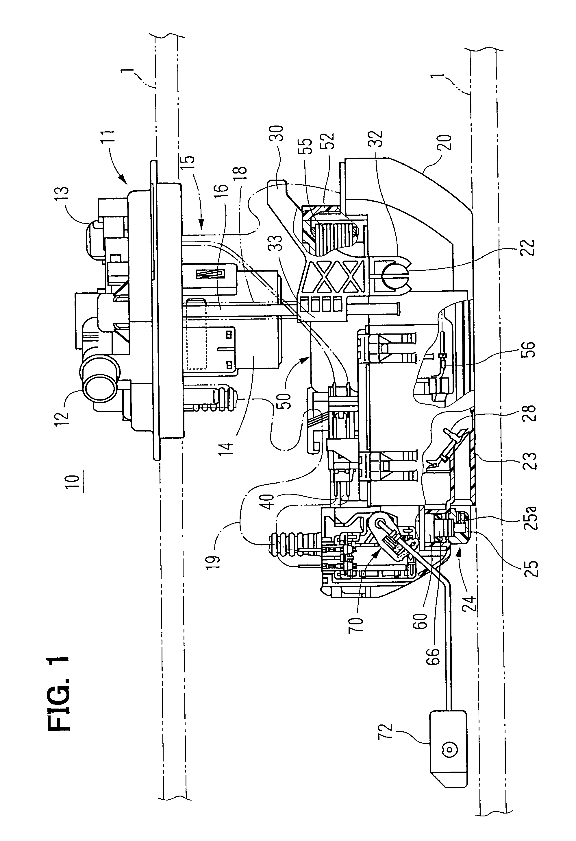
[0017]As shown in FIG. 1, a resinous flange 11 of a fuel feed apparatus 10 is mounted on a top wall of a resinous fuel tank 1. Other members of the fuel feed apparatus 10 are accommodated in the fuel tank 1. The flange 11 is used as a mounting member. An outlet pipe 12, an electric connector 13 and a vent valve 14 are built on the flange 11. The outlet pipe 12 is for supplying fuel discharged from a fuel pump 40 to outside the fuel tank 1. The fuel pump 40 is disposed in a sub tank 20. The outlet pipe 12 is connected with a pressure regulator 60 via a flexible tube 19. The pressure regulator 60 is provided on an outlet side of the fuel pump 40.

[0018]The connector 13 includes terminals for supplying electric power of the fuel pump 40 and a detection signal of a level sensor 70. The connector 13 has a grounding terminal for grounding the fuel feed apparatus 10. An electric part of the fuel pump 40, a grounding terminal 56 provided in the fuel filter 50 and the level ...

second embodiment

(Second Embodiment)

[0035]As shown in FIG. 3, a fuel feed apparatus 80 includes a flange 82, a sub tank 90, a pump module 100, a pressure regulator 120, and a jet pump 130. A fuel pump 102 is vertically disposed in the sub tank 90, differently from the fuel pump 40 according to the first embodiment.

[0036]The flange 82 used as a lid of the fuel feed apparatus 80 is formed in a disk-shape, and is mounted on the top wall of a fuel tank 101, and covers the opening of the fuel tank 101. Members of the fuel feed apparatus 80 are included in the fuel tank 101 except for the flange 82. An outlet pipe 83 and a connector 84 are built on the flange 82. The outlet pipe 83 is for supplying fuel discharged from the fuel pump 102 disposed inside the sub tank 90 to the outside of the fuel tank 101. The outlet pipe 83 is connected with a pressure regulator 120 through a flexible tube 88. The pressure regulator 120 adjusts pressure of fuel discharged from the fuel pump 102. The connector 84 includes t...


PUM

PropertyMeasurementUnit
suction pressureaaaaaaaaaa
conductiveaaaaaaaaaa
areaaaaaaaaaaa

Abstract

A fuel feed apparatus includes a grounded conductive resinous sub tank, a conductive fuel inlet pipe integrally formed with a bottom section of the sub tank and a conductive resinous jet nozzle included in a jet pump. The jet nozzle is welded on the bottom section of the sub tank, and has a nozzle port for jetting fuel. Here, the jet nozzle, the jet pump and the fuel inlet pipe are grounded via the sub tank without individual wiring member. Even if static electricity is generated due to friction between the jet nozzle and fuel jetted from the nozzle port, electrical charging can be prohibited. Thus, dielectric breakdown due to the electrically charging and cracking resulting from the dielectric breakdown can be also prohibited.

Description

CROSS REFERENCE TO RELATED APPLICATION[0001]This application is based on Japanese Patent Applications No. 2002-304139 filed on Oct. 18, 2002 and No. 2003-297113 filed on Aug. 21, 2003, the disclosure of which is incorporated herein by reference.BACKGROUND OF THE INVENTION[0002]The present invention relates to a fuel feed apparatus where fuel is supplied into a sub tank by a jet pump and sucked by a fuel pump to be discharged.[0003]In general, an in-tank type fuel feed apparatus is disposed in a fuel tank for sucking fuel in the fuel tank and discharging the fuel. In such a fuel feed apparatus, fuel is apt to be charged with static electricity caused by friction between fuel discharged by a fuel pump in the fuel feed apparatus and a fuel outlet pipe, or between fuel discharged by a fuel pump and a filter element in a fuel filter. When fuel discharged by the fuel pump is charged with static electricity, members defining a passage downstream of the fuel pump and peripheral members arou...

Claims


Application Information

Patent Timeline
Patent Type & Authority Patents(United States)
IPC IPC(8): F02M37/04B60K15/077F02M37/00F02M37/08F02M37/10F02M37/18F02M37/22F02M69/00
CPCB01D35/027F02M37/103B01D35/26B01D2201/50F02M37/106F02M2037/082
Inventor OKADA, KINGO
Owner DENSO CORP
Why Eureka
Try Eureka