
Head stabilizing system

a stabilizing system and head technology, applied in the direction of eye treatment, pedestrian/occupant safety arrangement, vehicular safety arrangment, etc., can solve the problems of high speed, high risk of severe head and neck injuries, and rapid deceleration of the vehicle, so as to reduce the net force on the head

Inactive Publication Date: 2007-01-02
BHC ENG
View PDF21 Cites 54 Cited by
  • Summary
  • Abstract
  • Description
  • Claims
  • Application Information

AI Technical Summary

Problems solved by technology

Activities that involve high speed, such as racing cars or boats and flying aircraft, involve a large risk of a high speed crash.
Such crashes involve rapid deceleration of the vehicle and the portion of its occupant connected, via seatbelt or harness, to the vehicle.
However, the head and the neck of the occupant are generally not connected to the seat, and thus the head of the occupant accelerates rapidly with respect to the body, exerting a large force on the base of the skull, the neck muscles, ligaments, and the spinal cord of the occupant, and creating a large risk for severe head and neck injuries.
Injuries caused by violent head movement were the most common cause of death among race car drivers during the last decade.
When the head accelerates rapidly with respect to the body, large loads on the neck will occur, commonly resulting in basilar skull fracture, a condition in which the base of the skull cracks from stress, often causing trauma to arteries and the spinal cord.
Many of these devices restrict movement of the wearer during normal use, making the devices cumbersome and even dangerous to wear, due, for example, to their potential for limiting driver visibility, interference with control of the vehicle, or inhibiting the wearer's ability to exit the vehicle in the event of fire.

Method used


Image

  • Head stabilizing system
  • Head stabilizing system
  • Head stabilizing system

Examples


Embodiment Construction

[0002]1. Field of the Invention

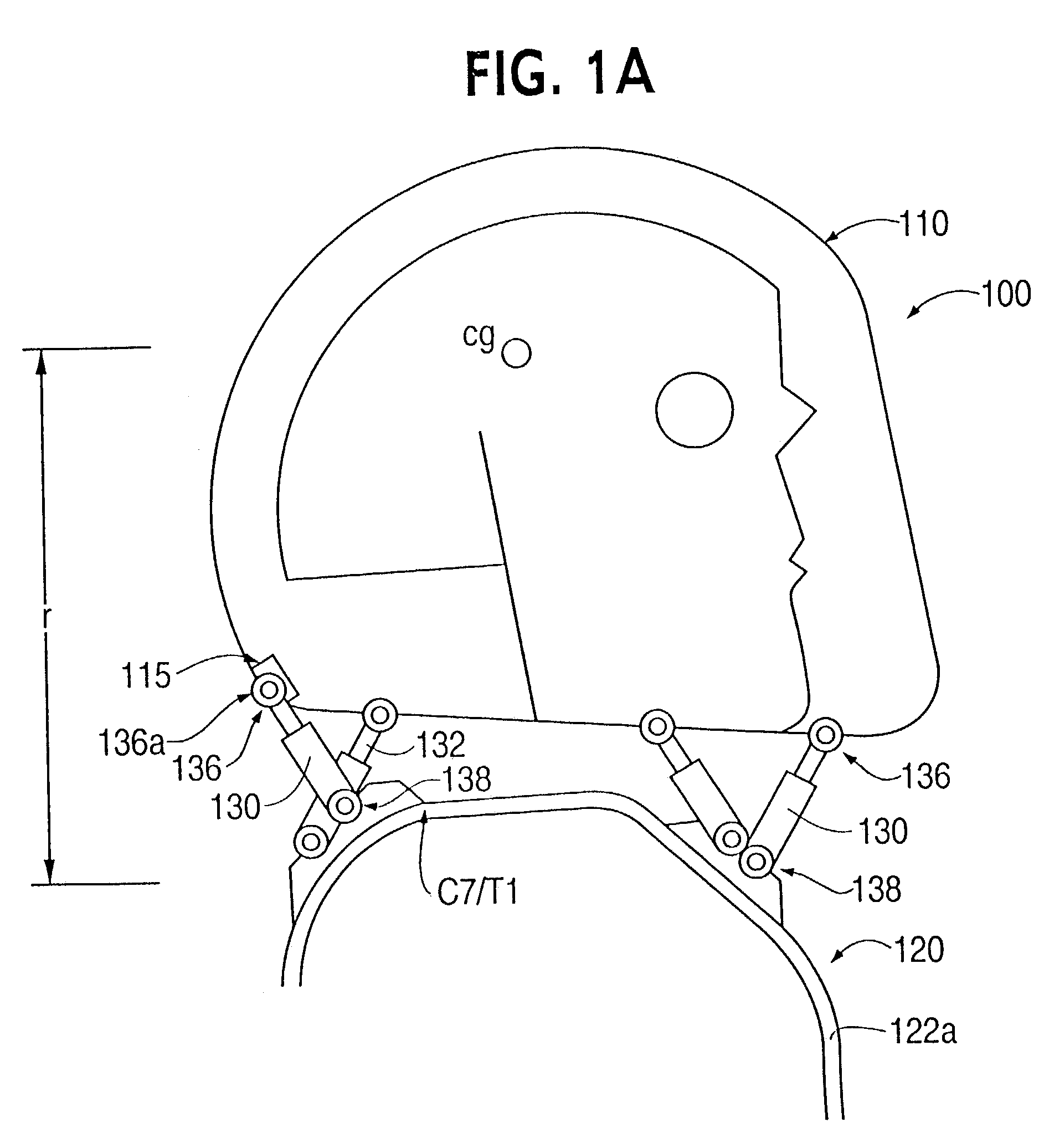
[0003]The present invention relates to a head stabilizing system for minimizing loads on the head and the neck, some of which may be injurious or even fatal, by generating a reaction force that substantially opposes a force acting on the head and generated by rapid deceleration of a vehicle or a crash impact.

[0004]2. Background of the Invention

[0005]Activities that involve high speed, such as racing cars or boats and flying aircraft, involve a large risk of a high speed crash. Such crashes involve rapid deceleration of the vehicle and the portion of its occupant connected, via seatbelt or harness, to the vehicle. However, the head and the neck of the occupant are generally not connected to the seat, and thus the head of the occupant accelerates rapidly with respect to the body, exerting a large force on the base of the skull, the neck muscles, ligaments, and the spinal cord of the occupant, and creating a large risk for severe head and neck injuries. I...


PUM


Abstract

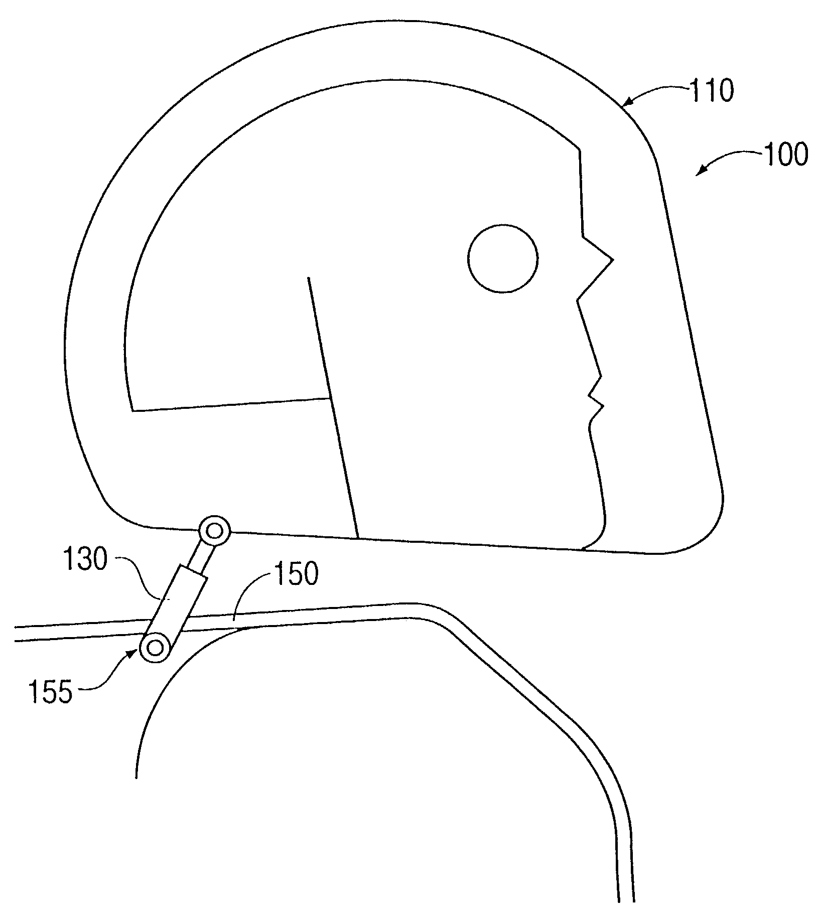
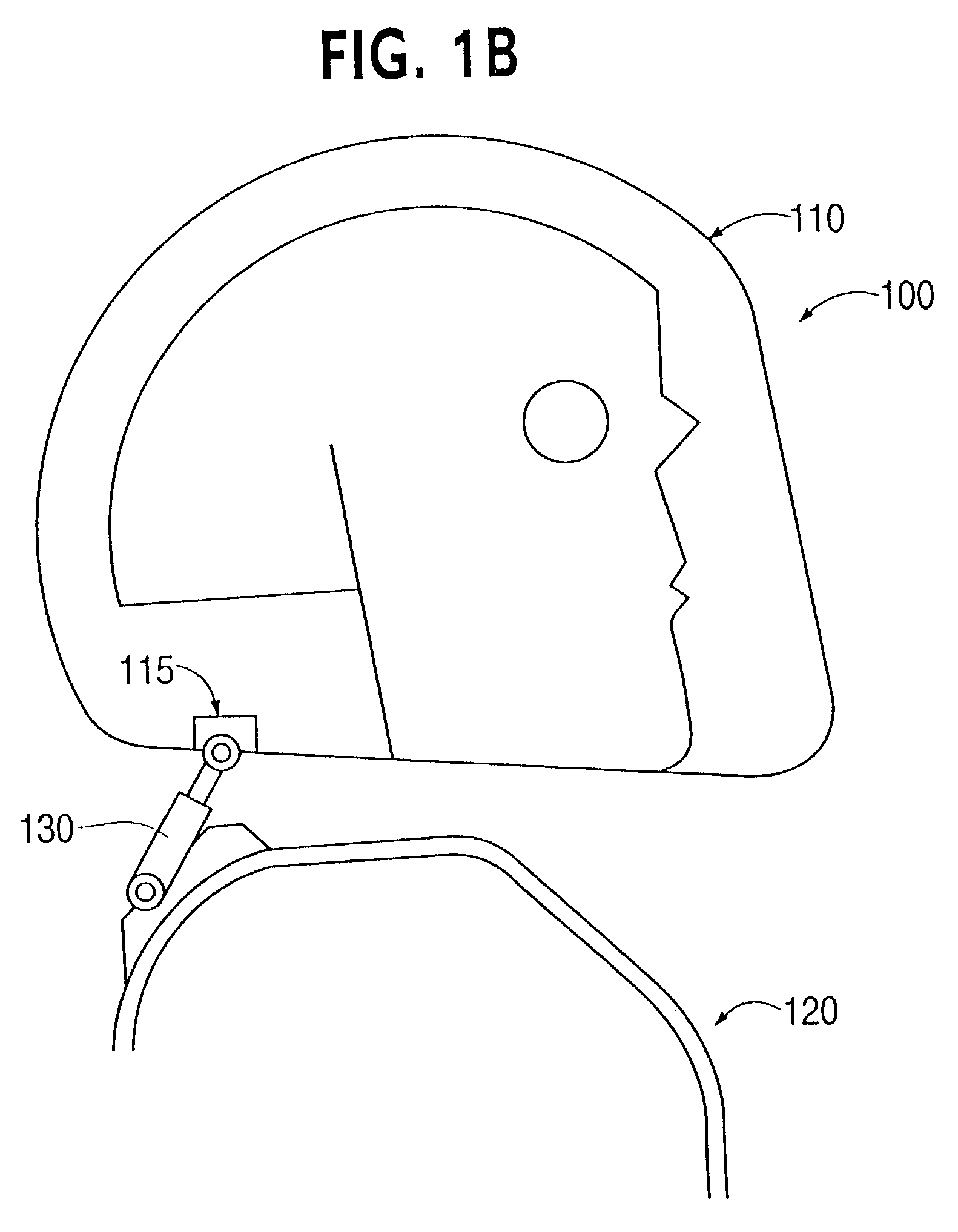
A head stabilizing system is provided. The head stabilizing system is intended to minimize loads on the head and the neck, some of which may be injurious or even fatal, by generating a reaction force that substantially opposes a force acting on the head and generated by rapid deceleration of a vehicle or a crash impact. The head stabilizing system includes a helmet, a connection structure, and at least one resisting member. The resisting member generates a reaction force that opposes the crash impact force, yielding a reduced net force on the head. This reaction force can be generated as a function of position, velocity or acceleration. The resisting member may include a tether, a dashpot, or a dashpot containing a controllable rheological fluid. The viscosity of the controllable rheological fluid can be automatically adjusted in response to changes in status of a vehicle or it's occupant.

Description

[0001]This application claims priority under 35 U.S.C. §119 based on U.S. Provisional Application No. 60 / 312,754, filed Aug. 17, 2001, and U.S. Provisional Application No. 60 / 315,359, filed Aug. 29, 2001, the complete disclosures of which are incorporated herein by reference.DESCRIPTION OF THE INVENTION[0002]1. Field of the Invention[0003]The present invention relates to a head stabilizing system for minimizing loads on the head and the neck, some of which may be injurious or even fatal, by generating a reaction force that substantially opposes a force acting on the head and generated by rapid deceleration of a vehicle or a crash impact.[0004]2. Background of the Invention[0005]Activities that involve high speed, such as racing cars or boats and flying aircraft, involve a large risk of a high speed crash. Such crashes involve rapid deceleration of the vehicle and the portion of its occupant connected, via seatbelt or harness, to the vehicle. However, the head and the neck of the occ...

Claims


Application Information

Patent Timeline
Patent Type & Authority Patents(United States)
IPC IPC(8): A42B1/24A42B3/04B60R21/00B60R21/02
CPCA42B3/0473B60R21/02B60R2021/0206B60R2021/0048
Inventor BAKER, GREGG S.
Owner BHC ENG
Learn More