
Robot obstacle detection system

a robot and obstacle detection technology, applied in the field of autonomous robot obstacle detection systems, can solve the problems of complex, expensive and power requirements of these types of robotic subsystems, unsuitable for the consumer market, and available sensor subsystems such as sonar sensors for detecting obstacles on or in the floor or the wall, etc., and achieves low cost, simple design, and easy implementation.

Inactive Publication Date: 2006-12-26
IROBOT CORP
View PDF351 Cites 400 Cited by
  • Summary
  • Abstract
  • Description
  • Claims
  • Application Information

AI Technical Summary

Benefits of technology

[0006]It is therefore an object of this invention to provide a robot obstacle detection system which is simple in design, low cost, accurate, easy to implement, and easy to calibrate.
[0007]It is a further object of this invention to provide such a robot detection system which prevents an autonomous cleaning robot from driving off a stair or obstacle which is too high.
[0008]It is a further object of this invention to provide a robotic wall detection system which is low cost, accurate, easy to implement and easy to calibrate.
[0009]It is a further object of this invention to provide such a robot wall detection system which effects smoother robot operation in the wall following mode.
[0012]The invention results from the realization that a low cost, accurate, and easy to implement system for either preventing an autonomous cleaning robot from driving off a stair or over an obstacle which is too high or too low and / or for more smoothly causing the robot to follow a wall for more thorough cleaning can be effected by intersecting the field of view of a detector with the field of emission of a directed beam at a predetermined region and then detecting whether the floor or wall occupies that region. If the floor does not occupy the predefined region, a stair or some other obstacle is present and the robot is directed away accordingly. If a wall occupies the region, the robot is first turned away from the wall and then turned back towards the wall at decreasing radiuses of curvature until the wall once again occupies the region of intersection to effect smoother robot operation in the wall following mode.

Problems solved by technology

Although technology exists for complex robots which can, to some extent, “see” and “feel” their surroundings, the complexity, expense and power requirements associated with these types of robotic subsystems render them unsuitable for the consumer marketplace.
Unfortunately, however, presently available sensor subsystems such as sonar sensors for detecting obstacles on or in the floor or for detecting the wall in order to enter the wall following mode (or to avoid bumping into the wall) are either too complex or too expensive of both.
Tactile sensors are inefficient.

Method used


Image

  • Robot obstacle detection system
  • Robot obstacle detection system
  • Robot obstacle detection system

Examples


Embodiment Construction

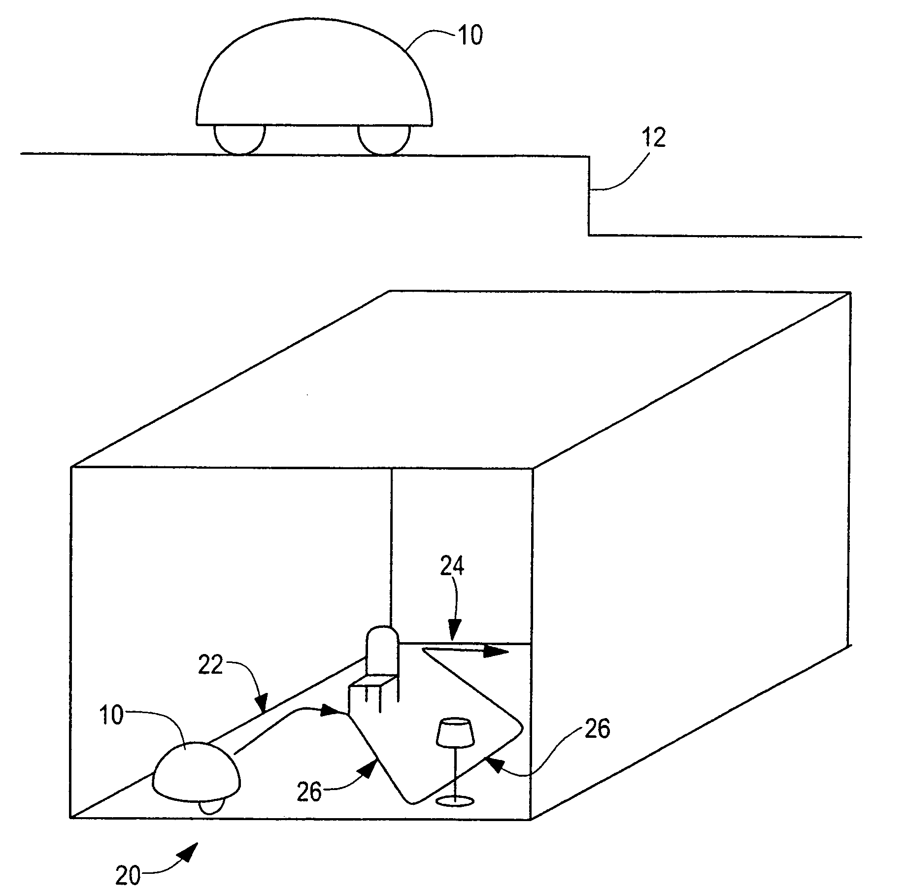
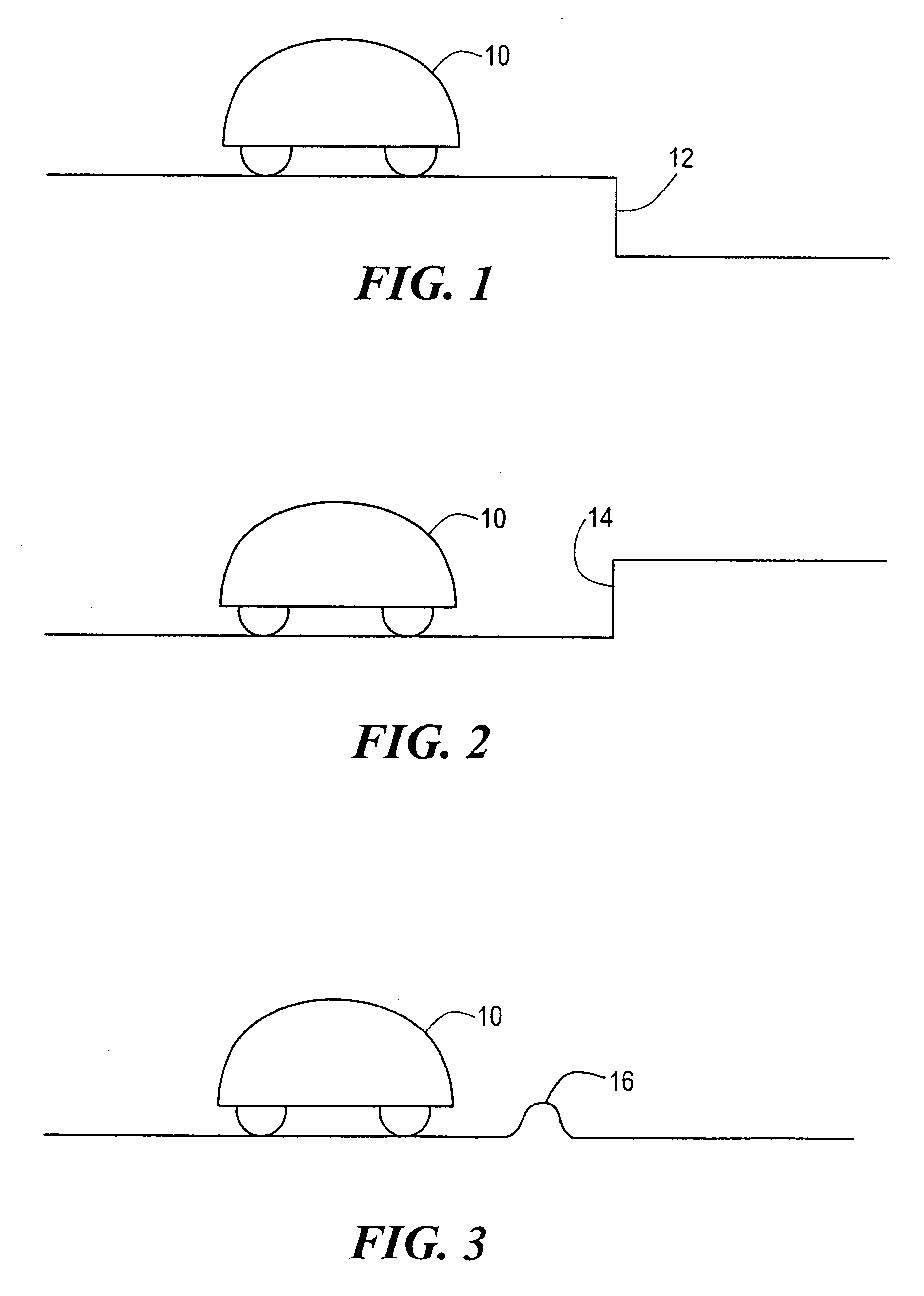
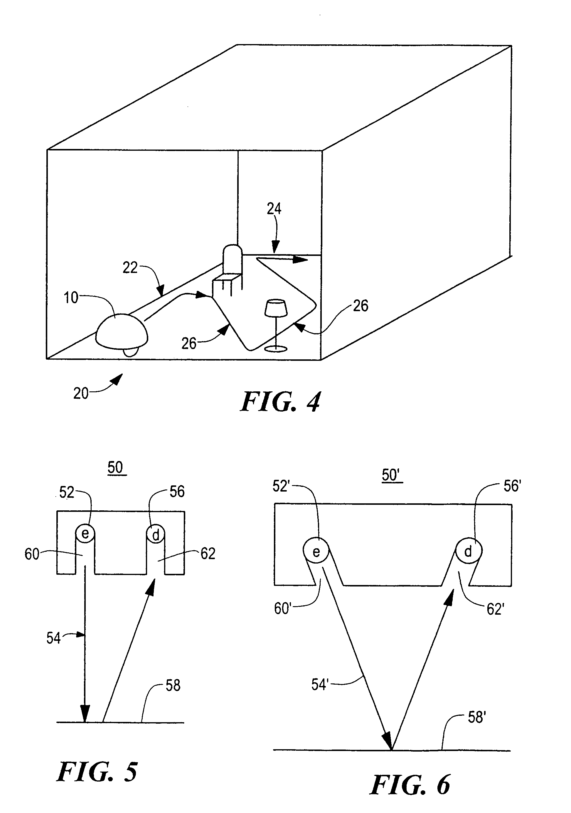
[0059]Robotic cleaning device 10, FIG. 1 can be configured to dust, mop, vacuum, and / or sweep a surface such as a floor. Typically, robot 10 operates in two modes: random coverage and a wall following mode as discussed in the Background section above. In either mode, robot 10 may encounter downward stair 12 or another similar “cliff”, upward stair 14, FIG. 2 or another similar rise, and / or obstacle 16, FIG. 3. According to one specification, the robot must be capable of traversing obstacles less then ⅝” above or below floor level. Therefore, robot 10 must avoid stairs 12 and 14 but traverse obstacle 16 which may be an extension cord, the interface between a rug and hard flooring, or a threshold between rooms.

[0060]As delineated in the background of the invention, presently available obstacle sensor subsystems useful in connection with robot 10 are either too complex or too expensive or both. Moreover, robot 10, FIG. 4 is designed to be inexpensive and to operate based on battery pow...


PUM


Abstract

A robot obstacle detection system including a robot housing which navigates with respect to a surface and a sensor subsystem having a defined relationship with respect to the housing and aimed at the surface for detecting the surface. The sensor subsystem includes an optical emitter which emits a directed beam having a defined field of emission and a photon detector having a defined field of view which intersects the field of emission of the emitter at a region. A circuit in communication with a detector redirects the robot when the surface does not occupy the region to avoid obstacles. A similar system is employed to detect walls.

Description

PRIORITY CLAIM[0001]This application is a continuation-in-part application of patent application Ser. No. 09 / 768,773 filed Jan. 24, 2001 now U.S. Pat. No. 6,594,844 which claims priority from Provisional Application Ser. No. 60 / 177,703 filed Jan. 24, 2000. This application is also related to patent application Ser. No. 10 / 167,851 and International Publication No. WO 02 / 101477 A2 both incorporated herein by this reference.FIELD OF THE INVENTION[0002]This invention relates to an obstacle detection system for an autonomous robot, such as an autonomous cleaning robot.BACKGROUND OF THE INVENTION[0003]There is a long felt need for autonomous robotic cleaning devices for dusting, mopping, vacuuming, and sweeping operations. Although technology exists for complex robots which can, to some extent, “see” and “feel” their surroundings, the complexity, expense and power requirements associated with these types of robotic subsystems render them unsuitable for the consumer marketplace.[0004]The a...

Claims


Application Information

Patent Timeline
IPC IPC(8): G06F19/00G05D1/02
CPCG05D1/0238G05D1/024G05D2201/0203G05D2201/0215
Inventor JONES, JOSEPH L.
Owner IROBOT CORP
Learn More