
Sealed-off switchgear

Inactive Publication Date: 2006-12-19
HYDAC ELECTRONICS GMBH +1
View PDF13 Cites 13 Cited by
  • Summary
  • Abstract
  • Description
  • Claims
  • Application Information

AI Technical Summary

Benefits of technology

[0006]Objects of the present invention are to provide a compact switching device suitable, in particular for use in automotive technology, and permitting a long period of reliable operation even in high humidity.
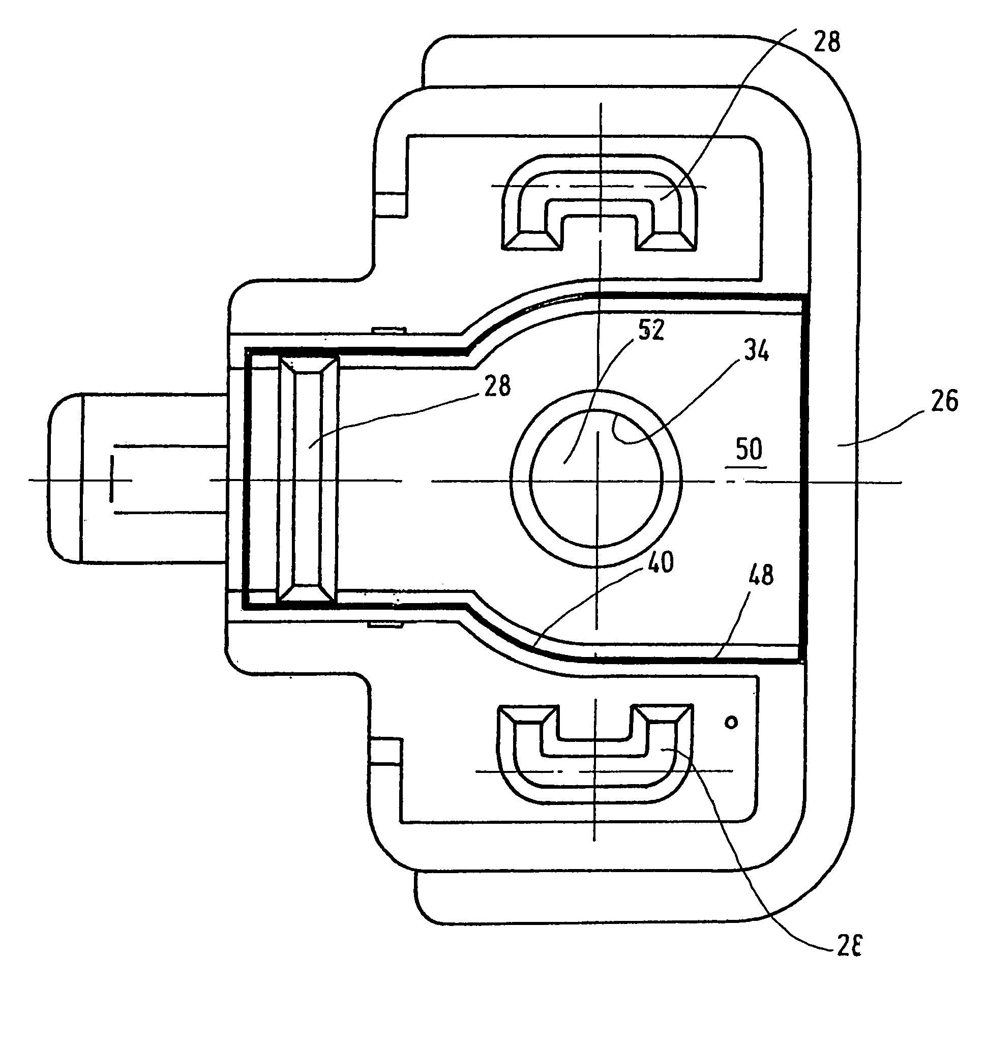
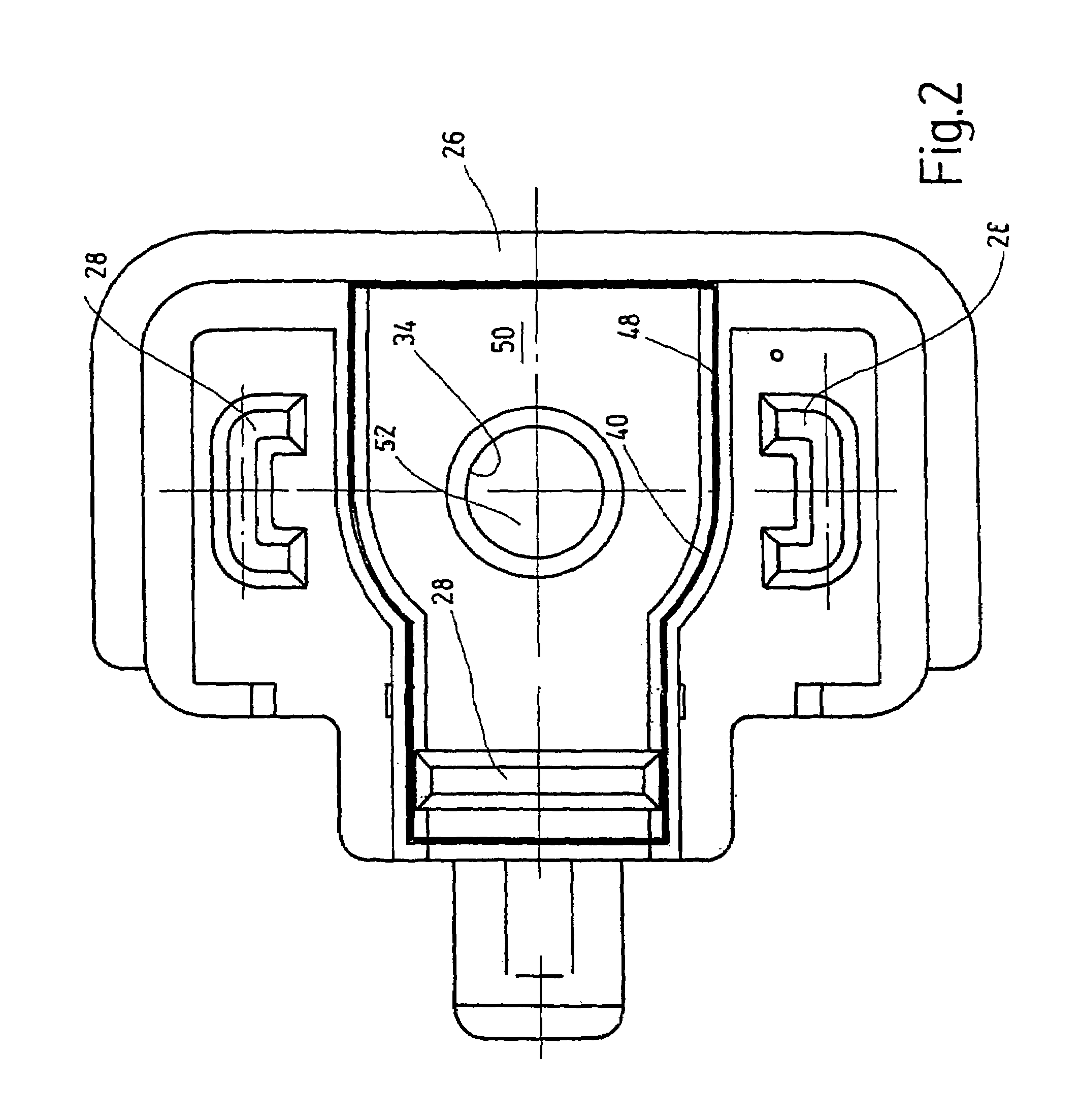
[0007]These objects are attained by a switching device according to the present invention where at least one of the sealing means is in the form of a sealing strip. The sealing strip is of a fusible material applied at a temperature such that the sealing strip melts with the plastic material to effect sealing from fluids, is mounted on the bottom of a plug receptacle of the plug connector facing the housing, and seals fluid tight from the environment, when melted and joined with the plastic material. At least the contact components of the plug connector are connected to the housing. The use of conventional rubber sealing rings (O rings), that are subject to failure, may be completely eliminated in the areas of the plug connector. Thermal fusion of the sealing strip to the plastic sealing compound results in homogenous fusion of material components facing each other, ensuring dependable sealing of the operating parts from the environment even in high humidity or penetration by condensate and ensuring dependable operation of the switching device even over very long periods of use. Since the sealing strip is distinctly compact, the sealing strips produced occupy no structural space or only a small such space. The sealing sections produced are themselves in turn small or occupy only a small structural space, so that the switching device as a whole or the switching magnet may be configured to be structurally small. Since the switching device is extrusion-coated with the plastic sealing compound, sealing of the device by the extrusion coating proper or casting integral with the plastic compound can be accomplished in one process step, something which appreciably simplifies production and lowers production costs. Consequently, the costly additional insertion of sealing rings and precise positioning of these rings inside the switching device in the area of the attaching plug may be completely eliminated.
[0009]Free space or a gap exists between the sealing strip and the housing or between the housing and the attaching plug. In extrusion coating by means of the hot plastic compound, the latter coating reaches the sealing strip unimpeded and flows around it on all sides until it is sealed off. Improved flow behavior is achieved for the plastic compound itself in jacketing of the switching device or essential parts of the latter. This flow behavior is favorable from the viewpoint of manufacturing technology. The use of additional sealing means in the form of rubber sealing rings or the like may be eliminated as a result of the sealing strip in the form of the fused strip in conjunction with the process of fusion with hot plastic compound.

Problems solved by technology

The moisture leads to disabling of the switching device as corrosion occurs.
While it has already been proposed to avoid this problem by enclosing the housing of the switching device entirely in a plastic sealing compound providing protection from moisture, this proposal results in an overly large switching device ill suited for use in automotive technology (mobile technology), where in essence only little installation space is available.
In this instance as well, however, it has been found that the sealing from penetration of moisture, in particular in the area of the plug connector of the connector plate, is not satisfactory.
Embrittlement of the sealing rings, which may accompany aging of the switching device, results in complete destruction of the sealing effect.
In this way, moisture can no longer reach the interior of the housing, and in particular the coil element with the winding.
This solution is costly to implement.
The parts in question must interact with minimal tolerances, something which appreciably increases manufacturing complexity and consequently manufacturing costs.
In addition, since a rubber sealing ring is used, when the switching device is in service over a long period failure from embrittlement or loosening of the sealing ring in question cannot be excluded.

Method used


Image

  • Sealed-off switchgear
  • Sealed-off switchgear
  • Sealed-off switchgear

Examples


Embodiment Construction

[0014]The switching device of the illustrated embodiment of the present invention has a coil element 10 of plastic material. The coil element 10 has on the end two annular frontal flanges 12 between which extends the winding stack 14 of a conductor 16, which in FIG. 1 is shown only in diagrammatic form. A switching component (not shown) is introduced into coil element 10, and is surrounded by a so-called polar tube (not shown). The configuration of the switching component and polar tube are conventional, and accordingly, will not be discussed in greater detail at this point. However, the switching component may be used in actuation of the switching device to operate conventional valves, and thus, to determine their switched position.

[0015]The coil element 10 is enclosed in a more or less cylindrical housing 18 of a metal material. The conductor 16 of the winding 14 is in contact with contact components (20) in the form of three plug lugs of an attaching plug 22 so as to conduct elec...


PUM


Abstract

A switchgear, especially for actuating valves, includes a housing (18) and a coil body (10) disposed in the housing. A switch element is guided in the coil body. The coil body is provided with a winding (14) of a conductor (16) that is connected to a plug connector (22) via contact elements (20). At least some sections of the housing (18) and of the plug connector (22) are enclosed by a plastic compound (24). Sealing devices (40) seal off the interior (42) of the switchgear from the surroundings (44). At least one of the sealing devices (40) is configured as a sealing web (48) of a meltable material. The sealing web (48) is disposed on the bottom face (50) of a plug plate (26) of the plug connector (22) which faces the housing (18). The sealing web (48), in the molten connection state, seals off at least the engaging parts of the plug connector (22) that are connected to the housing (18) from the surroundings (44) in a fluid-tight manner by the plastic compound (24), thereby eliminating the need for conventional rubber packing rings (O rings) in the area of the plug connector that are prone to failures.

Description

FIELD OF THE PRESENT INVENTION[0001]The present invention relates to a sealed-off switchgear, especially for actuating valves, comprising a housing and a coil element mounted in this housing. A switching component is conducted and is provided with a winding of a conductor which is connected to the contact components of an attaching plug. At least some parts of the housing and of the attaching plug are surrounded by a plastic material and means sealing the interior of the switching device from the environment.BACKGROUND OF THE INVENTION[0002]Switching devices, such as switchgears, are also designated as switching magnets, are disclosed, for example, in DE 36 35 551 A1 and DE-GM 83 17 753, and are readily obtainable on the market. The switching component is made up essentially of a tubular bolt which, when the coil undergoes electric excitation, traverses a predetermined path to the plug receptacle of a connector plate, thereby initiating a switching process, for example, in the case ...

Claims


Application Information

Patent Timeline
IPC IPC(8): H01F7/00F16K31/06H01F7/06H01F7/128
CPCH01F7/128
Inventor MULLER, MICHAELJACOBUS, HEINZSTITZ, MATTHIASSCHNEIDER, BRUNO
Owner HYDAC ELECTRONICS GMBH
Learn More