
Light-enhancing component and fabrication method thereof

a technology of light-enhancing components and fabrication methods, applied in the field of light-enhancing components, can solve the problems of slow scanning speed, limited scanning range, easy destruction of probes, etc., and achieve the effects of enhancing strength, narrowing width, and enhancing surface plasmon polaiton

Inactive Publication Date: 2006-12-12
NAT APPLIED RES LAB
View PDF18 Cites 21 Cited by
  • Summary
  • Abstract
  • Description
  • Claims
  • Application Information

AI Technical Summary

Benefits of technology

The present invention provides a light-enhancing component with extra high optical resolution and a fabrication method thereof. The component has a surface plasmon polariton structure coated on the surface of an optical fiber, which enhances the strength and narrows the width of the light transmitted through the fiber. This allows for improved light transmission and can be used for optical nano-lithography, detection, and biomedical applications.

Problems solved by technology

Due to the precise feedback control for the scanning system, the scanning velocity is slow, the scanning range is limited and the probe is easily destroyed.

Method used


Image

  • Light-enhancing component and fabrication method thereof
  • Light-enhancing component and fabrication method thereof
  • Light-enhancing component and fabrication method thereof

Examples


Embodiment Construction

[0018]The invention is described more specifically with reference to the following embodiments. It is to be noted that the following descriptions of preferred embodiments of this invention are presented herein for the purpose of illustration and description only; it is not intended to be exhaustive or to be limited to the precise form disclosed.

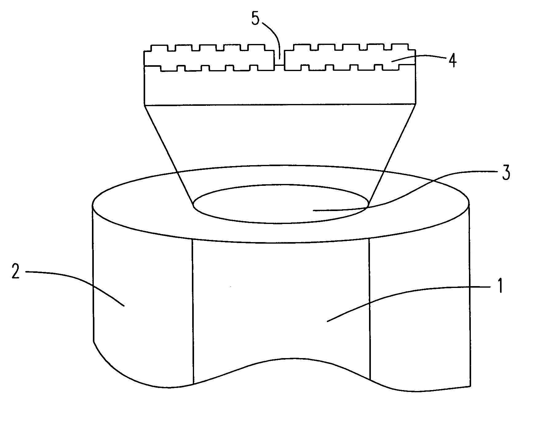
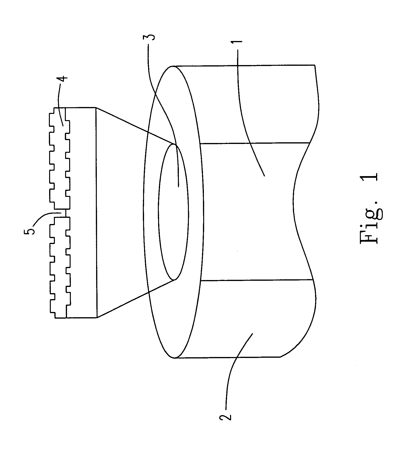
[0019]Please refer to FIG. 1 being the schematic view showing the structure of the light-enhancing component of the present invention, wherein the light-enhancing component includes a core 1, a cladding 2, a surface 3, a surface plasmon polariton structure 4 coated on the surface 3, and a nano-aperture 5 on the center of the surface plasmon polariton structure 4. The core 1 and the cladding 2 are made of SiO2 glass, doped SiO2 glass or the transparent polymer. The core 1 and the cladding 2 have the characteristics of the waveguide due to the variable refractive index of the material thereof. The core 1 can be a single-mode optical fiber, a mu...


PUM

PropertyMeasurementUnit
sizeaaaaaaaaaa
thicknessaaaaaaaaaa
periodic lengthaaaaaaaaaa

Abstract

The present invention provides a light-enhancing component and a fabrication method thereof by using the focused-ion-beam. In the present invention, the surface plasmon polariton structure is coated on the surface of the optical fiber so as to form the light-enhancing component. When the light passes through the optical fiber, the luminous flux transmitted through the aperture on the surface plasmon polariton is enhanced, and the light beam smaller than the diffraction limitation can be transmitted to the far-field, i.e. the nano-optic sword is formed. The light-enhancing component of the present invention can be used for the optical data storage, the optical microscopy, the biomedical detections and the lithography to perform the extra optical resolutions beyond the diffraction limitation.

Description

FIELD OF THE INVENTION[0001]The present invention relates to a light-enhancing component, and more particularly to the light enhancing component formed by a focused-ion-beam for enhancing the light beam transmitted to the far-field to be converged.BACKGROUND OF THE INVENTION[0002]Recently, in order to overcome the far-field diffraction limitation, the near-field scanning optical microscopy (NSOM) has been disclosed in U.S. Pat. No. 4,917,462, U.S. Pat. No. 5,894,122, U.S. Pat. No. 5,994,691, and U.S. Pat. No. 6,194,711, wherein NSOM is designed so that a probe whose aperture or radius of curvature of the tip is smaller than the wavelength of light used for measurement is placed close to the surface of a specimen, which is scanned with the probe to measure optical properties in a minute area of the specimen. NSOM is not restricted by the diffraction limit. For NSOM, while in a scattering probe, the resolving power corresponds to the order of the radius of curvature of the probe tip, ...

Claims


Application Information

Patent Timeline
Patent Type & Authority Patents(United States)
IPC IPC(8): G02B6/02B05D5/06C03B37/00G02B21/00
CPCB82Y20/00B82Y35/00G01Q60/22G02B6/262
Inventor CHEN, JYH-SHINFU, TONG-LONGCHENG, SHAO-CHANGLIN, YU-HSUANHU, YI-CHIUENLIN, HUI-HSIUNGCHOU, HSIAO-YU
Owner NAT APPLIED RES LAB
Learn More