
Continuous heart valve support frame and method of manufacture

a heart valve and support frame technology, applied in the field of medical devices, can solve the problems of unsightly bulge and reduce the overall life of the heart valve, and achieve the effect of eliminating any non-uniformity and being highly flexibl

Inactive Publication Date: 2006-11-21
EDWARDS LIFESCIENCES CORP
View PDF35 Cites 471 Cited by
  • Summary
  • Abstract
  • Description
  • Claims
  • Application Information

AI Technical Summary

Benefits of technology

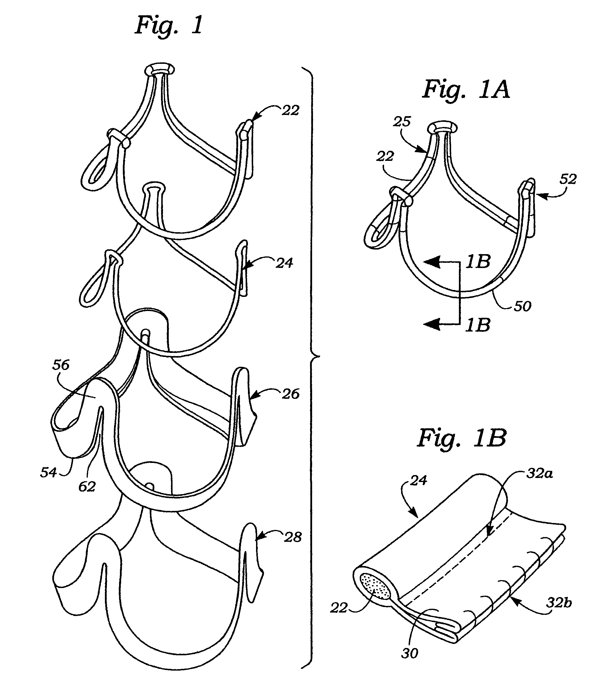
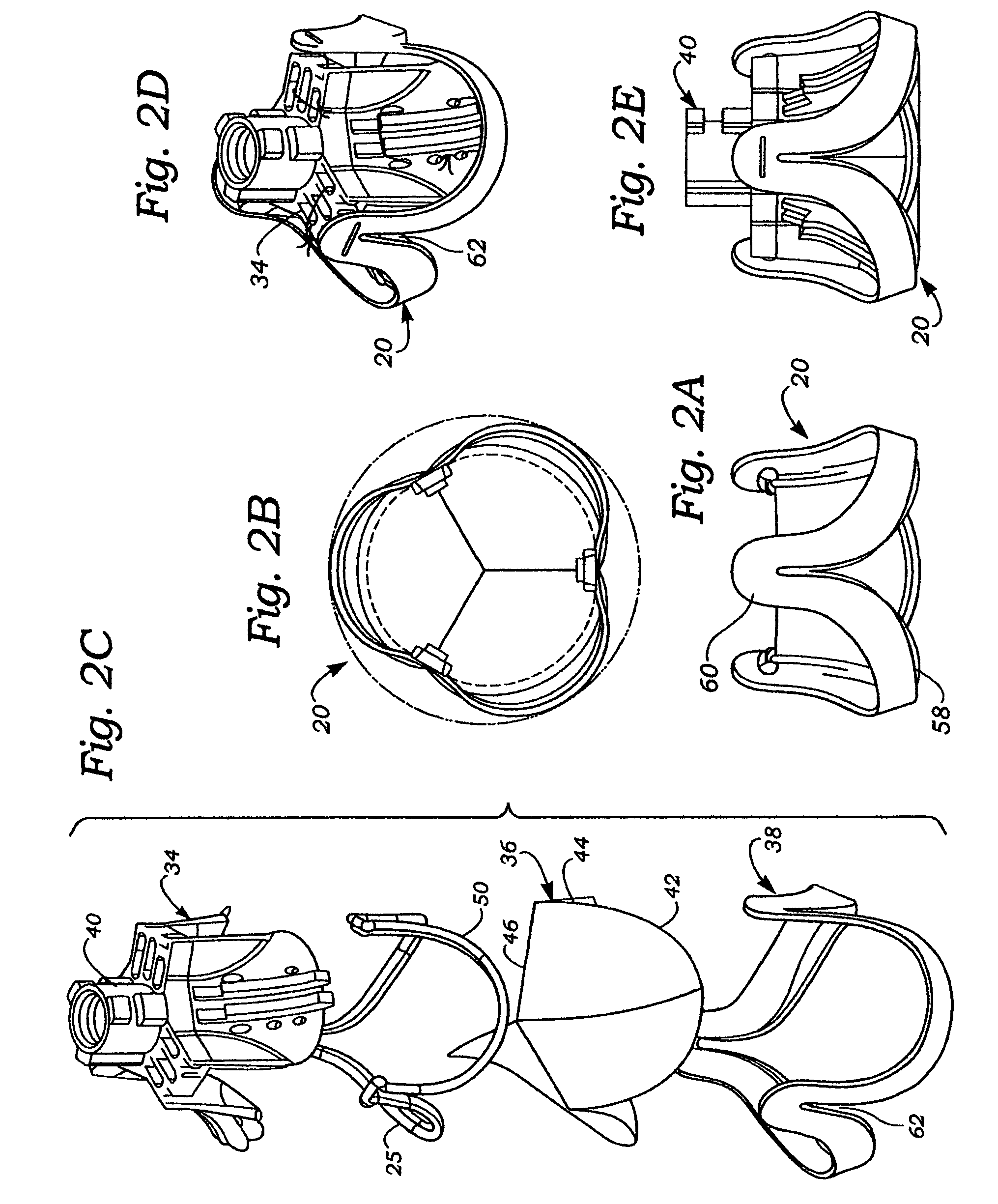
The present invention solves drawbacks associated with conventional spliced support frames or wireforms by providing a continuous, seamless heart valve support frame that eliminates non-uniformity in the periphery of the frame. The support frame is made of a superelastic material that can be forced into the desired shape and then altered to match the heart valve's exterior shape. The method of forming the support frame includes using a two-dimensional blank of the material and conforming it over a mandrel. The resulting heart valve support frame is flexible and can move with the dynamic pulsations of the surrounding cardiac tissue. The invention also provides several novel methods of forming the heart valve support frame. The heart valve support frame is designed to reduce stress concentration and can be surface treated to improve its performance. The invention also includes an intermediate apparatus for the formation of a prosthetic tissue-type heart valve.

Problems solved by technology

The plastic deformation of the splice and wire ends therewithin may cause high residual stresses, which can promote fatigue fracture of the support frame, thus reducing the overall life of the heart valve.
Further, the added diameter of the splice may create an unsightly bulge at one location around the valve circumference that may interfere with the implant process or provide a point of stress concentration.

Method used


Image

  • Continuous heart valve support frame and method of manufacture
  • Continuous heart valve support frame and method of manufacture
  • Continuous heart valve support frame and method of manufacture

Examples


Embodiment Construction

[0045]The present invention provides an improved support frame, forming apparatus, and method as described herein and shown in the accompanying drawings.

[0046]The present invention pertains primarily to flexible leaflet heart valve support frames, which are also referred to in the art as stents or wireforms. As mentioned above, the flexible leaflets can be provided by a biological (i.e., xenograft) valve, biological leaflets, or synthetic leaflets. In this context, a “support frame” for a flexible leaflet heart valve provides the primary internal structural support for the leaflets, and substantially mimics the natural fibrous skeleton of the respective valve annulus. More specifically, each of the leaflets has an outer edge that is coupled to a portion of the support frame such that its inner edge is free to move within the orifice area of the valve, thus providing the opening and closing surfaces thereof. In the common three-leaflet prosthetic valves, the support frame has an undu...


PUM

PropertyMeasurementUnit
voltageaaaaaaaaaa
temperatureaaaaaaaaaa
thicknessaaaaaaaaaa

Abstract

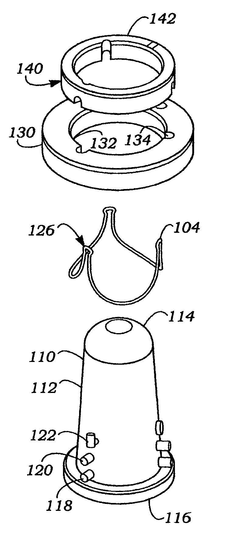
Methods for forming a support frame for flexible leaflet heart valves from a starting blank include converting a two-dimensional starting blank into the three-dimensional support frame. The material may be superelastic, such as NITINOL, and the method may include bending the 2-D blank into the 3-D form and shape setting it. A merely elastic material such as ELGILOY may be used and plastically deformed in stages, possibly accompanied by annealing, to obtain the 3-D shape. Alternatively, a tubular blank could be formed to define a non-tubular shape, typically conical. A method for calculating the precise 2-D blank shape is also disclosed. A mandrel assembly includes a mandrel and ring elements for pressing the blank against the external surface of the mandrel prior to shape setting.

Description

RELATED APPLICATIONS[0001]The present application is a continuation of U.S. application Ser. No. 10 / 251,651, filed on Sep. 20, 2002, now abandoned.FIELD OF THE INVENTION[0002]The present invention relates generally to medical devices, and more particularly to a continuous three-dimensional support frame for use in heart valves, and methods and apparatuses for forming such support frames.BACKGROUND OF THE INVENTION[0003]Two primary types of heart valve replacements or prostheses are known. One is a mechanical-type heart valve that uses a ball and cage arrangement or a pivoting mechanical closure to provide unidirectional blood flow. The other is a tissue-type or “bioprosthetic” valve which is constructed with natural tissue leaflets which function much like those in a natural human heart valve; that is, the leaflets imitate the natural action of the flexible leaflets that form commissures to seal against each other and ensure the one-way blood flow. In tissue valves, a whole xenograf...

Claims


Application Information

Patent Timeline
Patent Type & Authority Patents(United States)
IPC IPC(8): B23P11/02A61F2/24
CPCA61F2/2412A61F2/2415A61F2/2418A61F2220/0075Y10T29/49995Y10T29/49865Y10T29/49906Y10T29/49885Y10T29/49895Y10T29/49904Y10T29/49405
Inventor SCHRECK, STEFAN
Owner EDWARDS LIFESCIENCES CORP
Learn More