
Electroluminescent phosphor and its production method

a technology of electroluminescent phosphor and production method, which is applied in the field of electroluminescent phosphor, can solve the problems of affecting the luminance, unable to improve the luminance or life span of electroluminescent phosphor, and difficulty in introducing alkaline earth metal oxide into zinc sulfid

Inactive Publication Date: 2006-11-14
NEMOTO TOKUSHIYU KAGAKU KK
View PDF1 Cites 2 Cited by
  • Summary
  • Abstract
  • Description
  • Claims
  • Application Information

AI Technical Summary

Benefits of technology

"The invention is about an electroluminescent phosphor that has improved luminance and life span. This is achieved by adding a host material, an activator, a co-activator, and either chlorine, manganese, or both to the zinc sulfide. The host material can be represented by the formula ZnS.aAO, where \"a\" is a element selected from among magnesium, calcium, strontium, and barium. The activator can be copper or manganese, and the co-activator can be chlorine, bromine, iodine, or aluminum. The phosphor can be produced by a primary firing process, an intermediate manufacturing process, a secondary firing process, and an etching process. The use of magnesium oxide and specific compounds that change into alkaline earth metal oxides when fired as the host material and co-activator, respectively, improves the luminance and life span of the phosphor."

Problems solved by technology

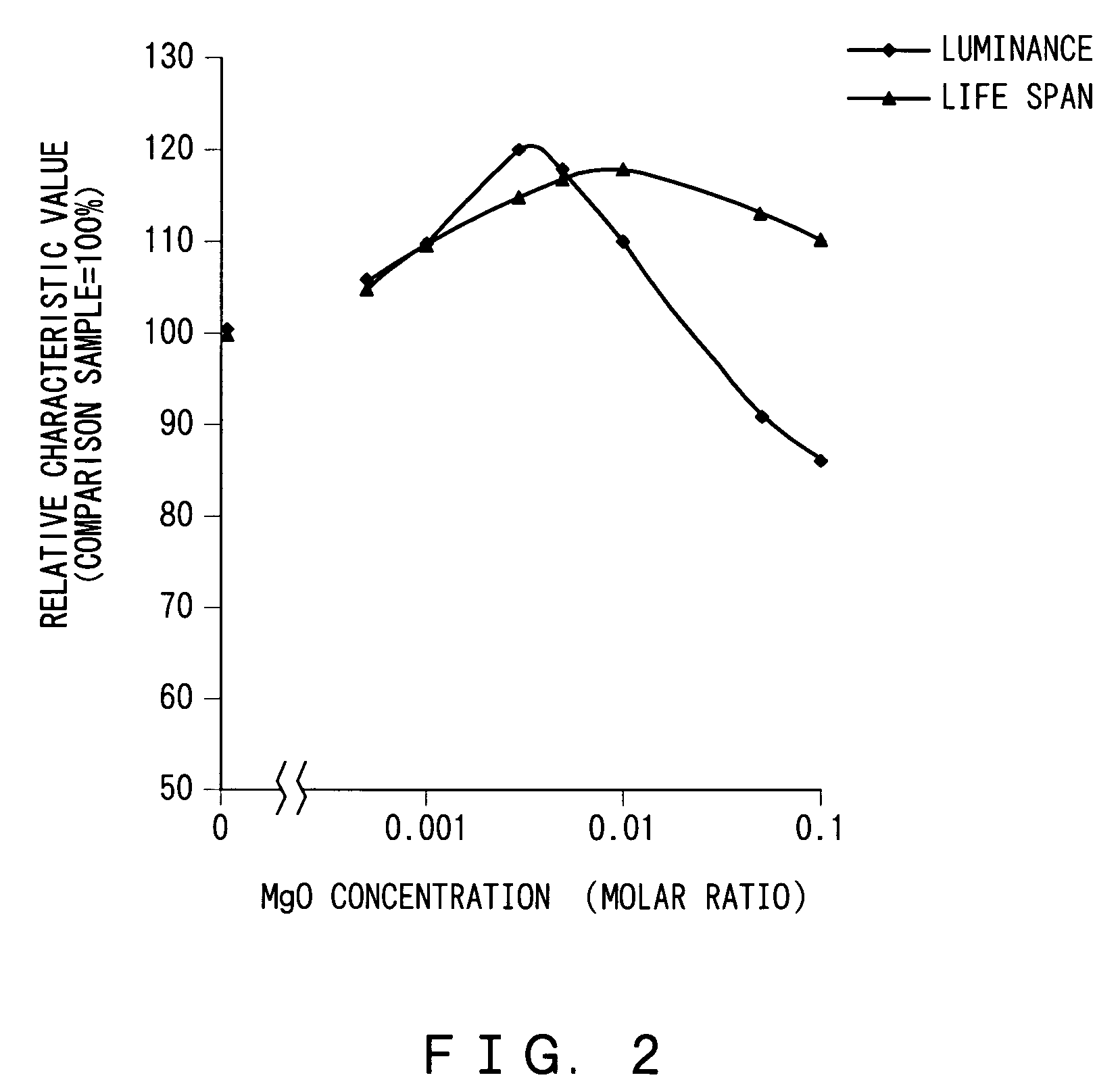
Should “a” exceed 0.01, the proportion of AO that does not contribute to emission of light increases and thereby impairs the luminance.
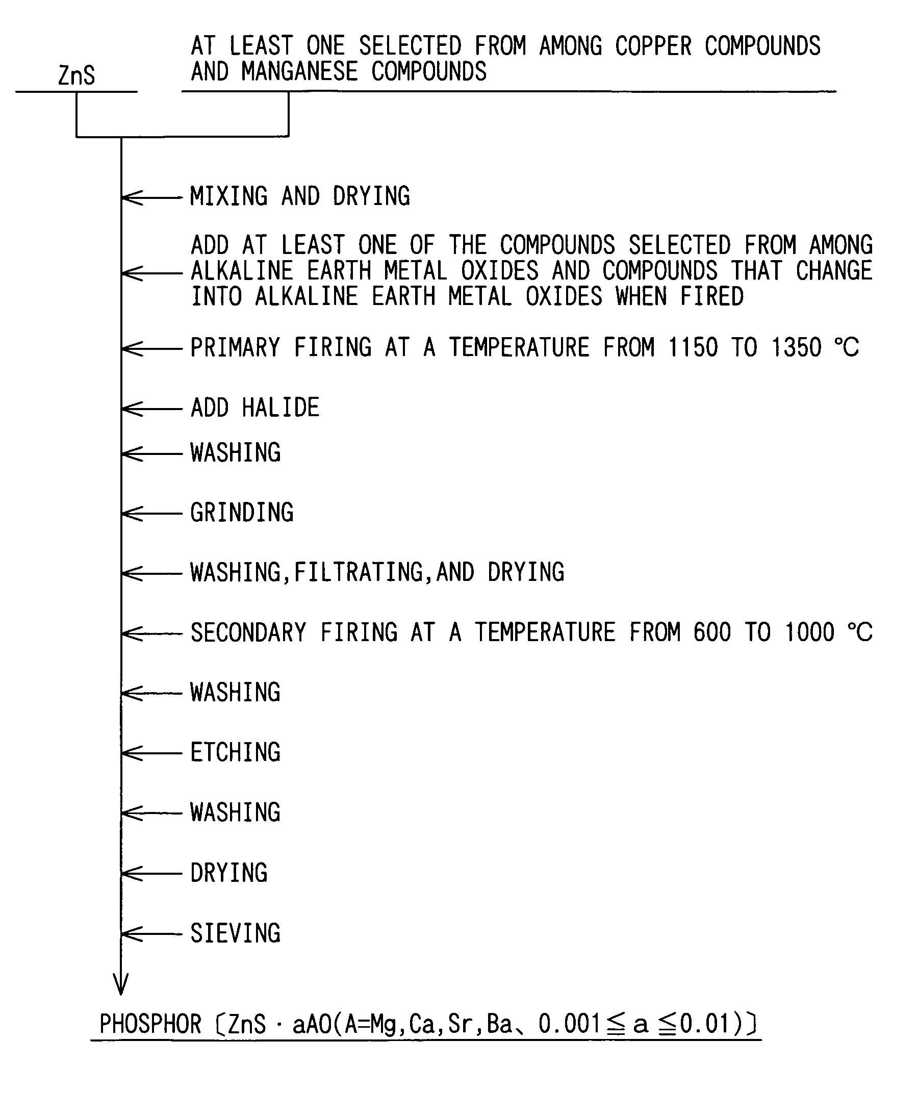
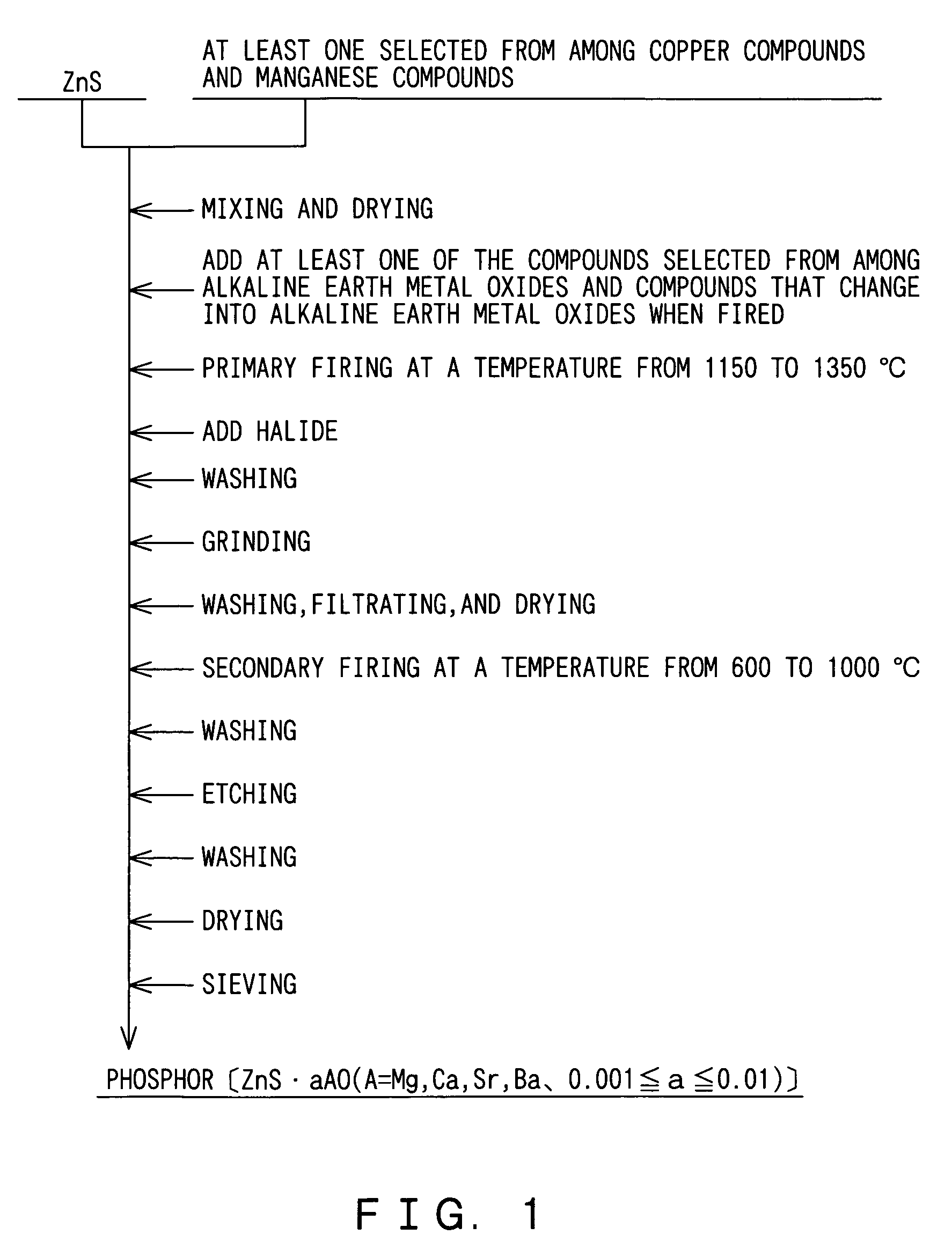
Should the firing temperature for the primary firing process be lower than 1150° C., neither the luminance nor life span of the electroluminescent phosphor is improved, because such a low temperature impairs progress of solid chemical reaction between the zinc sulfide and the alkaline earth metal oxide, making the introduction of the alkaline earth metal oxide into the zinc sulfide difficult.
A firing temperature higher than 1350° C. for the primary firing process would promote excessive growth of zinc sulfide particles, making control of particle size difficult, and also increases sublimation, resulting in reduced yield.

Method used


Image

  • Electroluminescent phosphor and its production method
  • Electroluminescent phosphor and its production method
  • Electroluminescent phosphor and its production method

Examples


working examples

[0028]Next, working examples according to the embodiment described above are explained.

[0029](Test 1)

[0030]First, a test was performed to evaluate the relationship between proportions of the alkaline earth metal oxide to the zinc sulfide and properties of electroluminescent phosphor, i.e. its luminance and life span.

[0031]In the manner described above, 500 g of zinc sulfide (ZnS) was dispersed in deionized water, and an aqueous solution of copper sulfate was mixed into the zinc sulfide-infused deionized water so as to make a mixture with copper concentration to the zinc sulfide being 0.05% by mass.

[0032]Thereafter, the mixture was dried at 120° C., and 0.62 g of magnesium oxide (MgO) was added to the mixture so that the molar ratio of the magnesium oxide to the zinc sulfide is 0.003. After chlorides that would serve as a crystal glowing agent, i.e. flux, are added to the mixture at a total mixing ratio of 8% by mass to the zinc sulfide, the mixture was thoroughly mixed. The chloride...


PUM

PropertyMeasurementUnit
temperatureaaaaaaaaaa
molar ratioaaaaaaaaaa
temperatureaaaaaaaaaa

Abstract

The invention provides electroluminescent phosphor having superior luminance and a long life. The host material is ZnS.aAO, of which “A” is at least one element selected from among magnesium (Mg), calcium (Ca), strontium (Sr), and barium (Ba). “a” ranges from 0.001 to 0.01. Either one of or both copper (Cu) or manganese (Mn) is contained as an activator. At least one element selected from among chlorine (Cl), bromine (Br), iodine (I), and aluminum (Al) is contained as a co-activator. The luminance and life span of the electroluminescent phosphor can be increased by limiting “a”, which represents the proportion of alkaline earth metal oxide (AO) introduced into the zinc sulfide, within the range of 0.001 to 0.01.

Description

FIELD OF THE INVENTION[0001]The present invention relates to electroluminescent phosphor with a host material that can be represented by the formula ZnS.aAO, wherein “A” is at least one element selected from among magnesium (Mg), calcium (Ca), strontium (Sr), and barium (Ba). The invention also relates to a method of producing such electroluminescent phosphor.BACKGROUND OF THE INVENTION[0002]A conventional organic dispersion electro luminescence (EL) element typically includes a luminescent layer, which is formed by dispersing electroluminescent phosphor in dielectric, and two electrodes respectively disposed at both sides of the luminescent layer so that the organic dispersion EL panel emits light when an AC voltage is applied between the electrodes. At least one of the electrodes is a transparent electrode. Such an organic dispersion EL panel is typically used in a back light of a cell phone or other displays.[0003]A typical example of electroluminescent phosphors used in organic ...

Claims


Application Information

Patent Timeline
Patent Type & Authority Patents(United States)
IPC IPC(8): C09K11/56C09K11/54C09K11/00H05B33/10C09K11/08C09K11/57C09K11/58H05B33/14
CPCC09K11/576C09K11/586
Inventor WATABE, JUNYAKANNO, YOSHIKIMATSUMURA, SHIGENOBU
Owner NEMOTO TOKUSHIYU KAGAKU KK
Learn More