
Power supply circuit having soft start

a power supply circuit and soft start technology, applied in the direction of electric variable regulation, process and machine control, instruments, etc., can solve the problems of excessive input current at startup, battery burden, battery cannot be fully used,

Inactive Publication Date: 2006-10-31
SHARP KK
View PDF10 Cites 80 Cited by
  • Summary
  • Abstract
  • Description
  • Claims
  • Application Information

AI Technical Summary

Benefits of technology

The present invention provides a power supply circuit that can limit excessive current flowing at startup and bring an output voltage to a desired level quickly. It uses a voltage booster method to increase the output voltage gradually and stabilize it. The circuit includes a soft-start circuit that prevents excessive current flow during startup and a circuit for detecting the output voltage and activating the soft-start circuit only during the first rising period of the external input signal. This ensures safe and stable operation of the circuit.

Problems solved by technology

When this happens and if the DC power source 1 is a battery such as a lithium-ion battery, a burden is placed on the battery.
Moreover, it is possible that the battery voltage drops due to the excessive amount of charging current, causing a problem in which the battery can not be fully used until the battery voltage reaches a discharge end voltage thereof.
As explained, the problem is that the input current Iin becomes excessive at startup (time to).
As a result, because an excessive current for charging the output capacitor 5 flows out from the DC power source 1 which is a battery in this example, a heavy burden is imposed on the battery.
At the same time, the battery voltage drops because of this excessive amount of charging current, preventing the battery from being used until the battery voltage reaches its original discharge end voltage.
For this reason, it is not possible to feed a constant output current Io through the white light-emitting diodes LED1 to LED6, and it is thereby difficult to perform a desired brightness control in accordance with a duty cycle of the brightness control signal.
However, when the switching power unit is repeatedly turned on and off at short intervals, an output voltage rises slowly every time it is turned on due to the soft-start operation and does not reach a desired voltage.
Therefore, it becomes difficult to perform a desired brightness control based on the duty cycle of the brightness control signal.
Furthermore, according to the conventional technology described in Japanese Patent Application Laid-Open No. 2000-324807, since a combination of the switches that can limit current and the switches that can prevent current from flowing for a certain period of time is used, the circuit becomes complicated, and it becomes difficult to control the output voltage according to the duty cycle of the brightness control signal.

Method used


Image

  • Power supply circuit having soft start
  • Power supply circuit having soft start
  • Power supply circuit having soft start

Examples


first embodiment

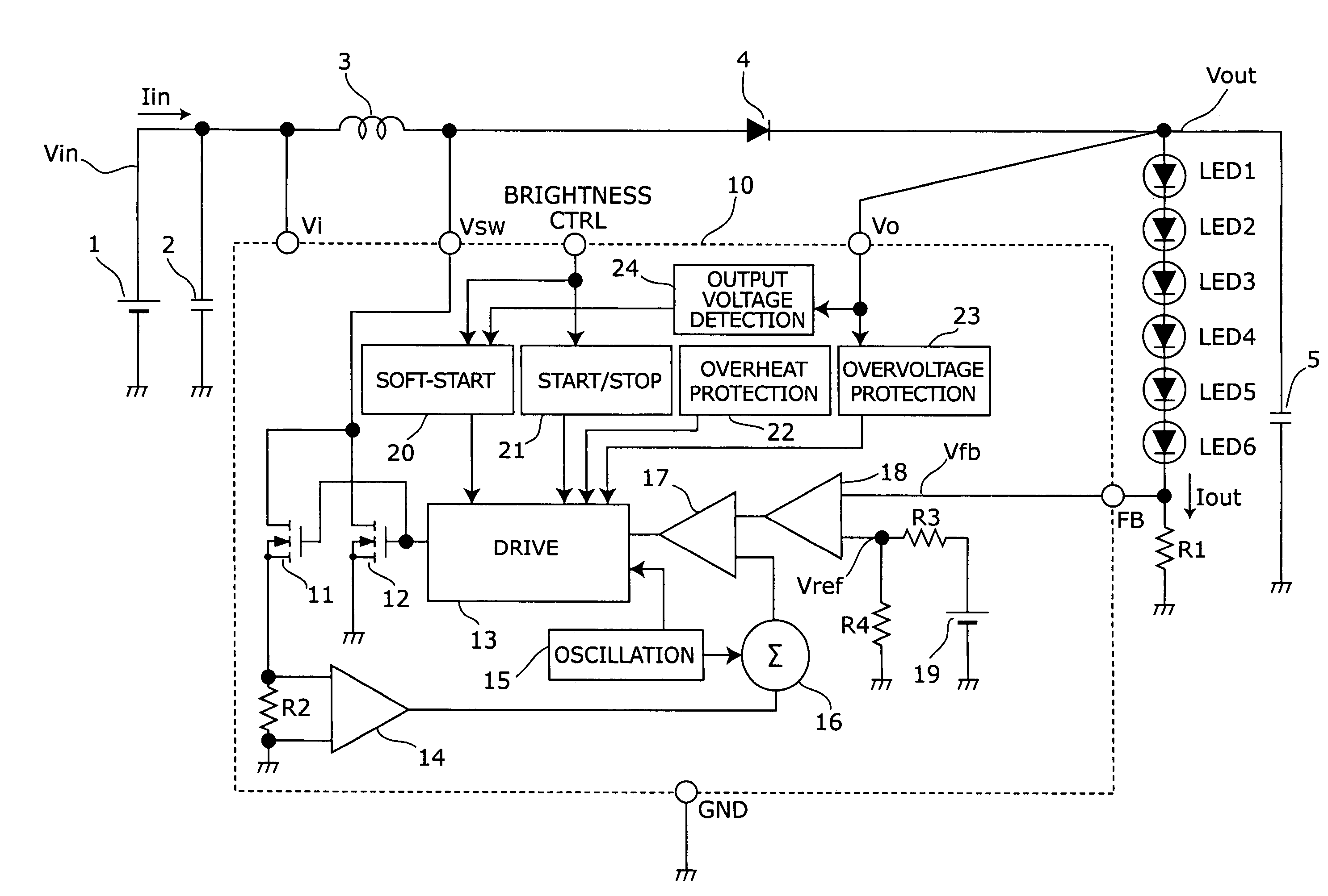
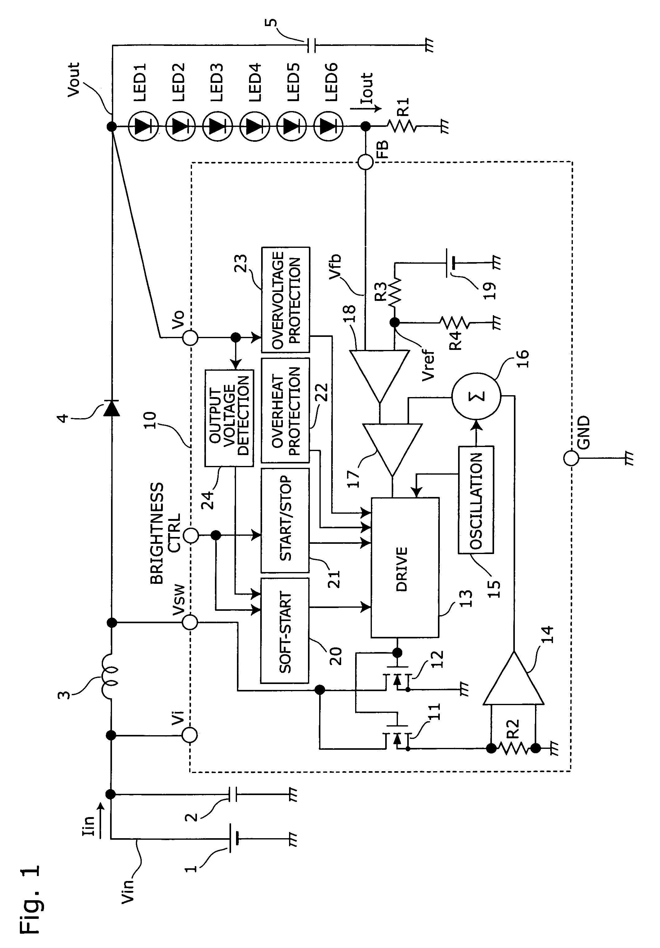
[0051]Hereinafter, embodiments of the present invention will be described with reference to the drawings. FIG. 1 is a circuit block diagram showing an electronic configuration of a power supply circuit of the invention. In FIG. 1, such components as are found also in FIG. 9 are identified with the same reference numerals and descriptions thereof will not be repeated. The power supply circuit shown in FIG. 1 is different from the power supply circuit shown in FIG. 9 and is additionally provided with an output voltage detection circuit 24 in the boost chopper regulator 10.

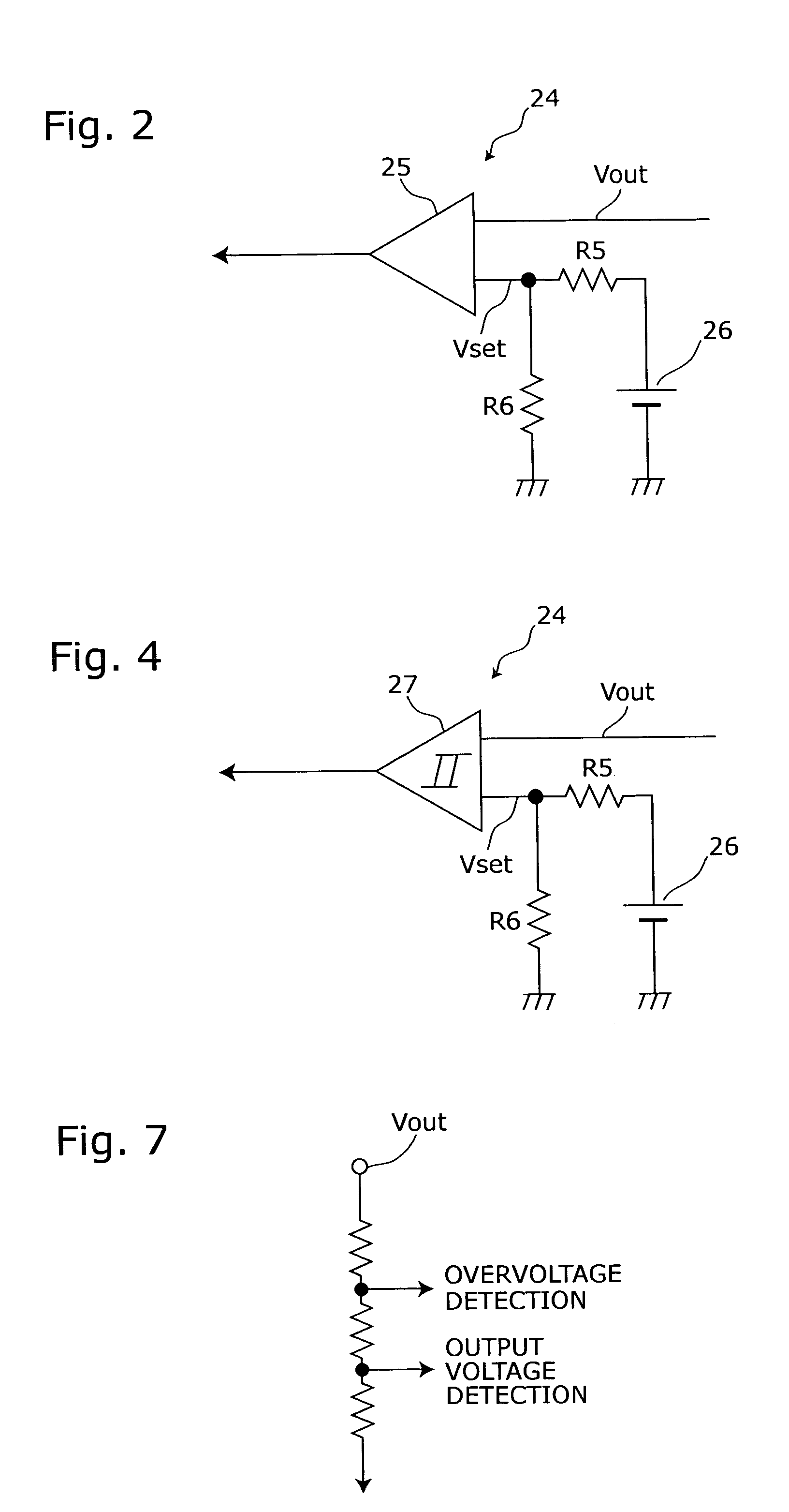
[0052]The output voltage detection circuit 24 is connected between the output voltage monitoring terminal Vo and the soft-start circuit 20 so as to compare the output voltage Vout fed through the output voltage monitoring terminal Vo with a set voltage Vset. A comparison result signal obtained thereby is then fed to the soft-start circuit 20. The output voltage detection circuit 24 described above can be configured b...

second embodiment

[0071]FIG. 5 is a circuit block diagram showing an electronic configuration of a power supply circuit of the invention. In FIG. 5, such components as are found also in FIG. 1 are identified with the same reference numerals and descriptions thereof will not be repeated. The power supply circuit shown in FIG. 5 is different from the power supply circuit shown in FIG. 1 and is provided with a feedback voltage detection circuit 28 instead of the output voltage detection circuit 24.

[0072]The feedback voltage detection circuit 28 is connected between the feedback terminal FB and the soft-start circuit 20, compares the feedback voltage Vfb fed through the feedback terminal FB with the set voltage Vset, and feeds the comparison result signal to the soft-start circuit 20. In the power supply circuit shown in FIG. 5, the voltage to be used for deciding whether the soft-start circuit 20 is turned to the operative state or the inoperative state is changed from the output voltage Vout in FIG. 1 ...

third embodiment

[0074]FIG. 6 is a circuit block diagram showing an electronic configuration of a power supply circuit of the invention. In FIG. 6, such components as are found also in FIG. 1 are identified with the same reference numerals and descriptions thereof will not be repeated. The power supply circuit shown in FIG. 6 is different from the power supply circuit shown in FIG. 1 and is provided with an overvoltage protection circuit 29 capable of performing the functions of the overvoltage protection circuit 23 and the output voltage detection circuit 24 shown in FIG. 1 as well.

[0075]The output voltage detection circuit 24 and the overvoltage protection circuit 23 shown in FIG. 1 feed out comparison result signals respectively after comparing the output voltage Vout with predetermined voltages preset for respective circuits. For this reason, the overvoltage protection circuit 29 shown in FIG. 6 can be easily realized by combining these two circuits. For example, as shown in FIG. 7, it can be re...


PUM


Abstract

The voltage booster type switching power supply circuit is provided with a drive circuit for controlling a switching element, a start / stop circuit for turning the drive circuit on and off according to a brightness control signal for adjusting a brightness of a light source of a liquid crystal display device, an output voltage detection circuit for detecting whether the output voltage is greater than a predetermined voltage and feeding out a result as a comparison result signal, and a soft-start circuit that does not operate when the comparison result signal is active on the rising edge of the brightness control signal, and that operates so as to increase the output voltage gradually when the comparison result signal is inactive on the rising edge of the brightness control signal.

Description

BACKGROUND OF THE INVENTION[0001]This nonprovisional application claims priority under 35 U.S.C. §119(a) on Patent Application No. 2003-393340 filed in Japan on Nov. 25, 2003, the entire contents of which are hereby incorporated by reference.FIELD OF THE INVENTION[0002]The present invention relates to a power supply circuit for supplying power by boosting an input voltage of a DC power source, and in particular, to a power supply circuit for repeating start / stop voltage boosting operations according to PWM (Pulse Width Modulation) signals.Description of the Prior Art[0003]An electronic apparatus such as a portable telephone, a PDA (Persona Digital Assistant), or a digital camera is equipped with a liquid crystal display (LCD). In recent years, a white light-emitting diode has been increasingly used as one of light sources (back light or front light) for the LCD due to its superior properties in durability, light-emitting efficiency, and space required thereby. The white light-emitti...

Claims


Application Information

Patent Timeline
Patent Type & Authority Patents(United States)
IPC IPC(8): G05F1/10H02H7/20H02H7/12H02M3/155H02M3/156H05B44/00
CPCH02M3/156H05B33/0815H02M1/36Y02B20/346Y10S323/901H05B45/38Y02B20/30
Inventor INABA, KATSUMISATOH, TSUTOMUWARITA, HIROHISAKANAMORI, ATSUSHI
Owner SHARP KK
Learn More