
Method and system for automated process correction using model parameters, and lithographic apparatus using such method and system

a technology of automatic process correction and model parameters, applied in the field of alignment of substrates, can solve the problems of large machine-related overlay errors, batch processing only further, troublesome off-line analysis,

Inactive Publication Date: 2006-10-24
ASML NETHERLANDS BV
View PDF3 Cites 19 Cited by
  • Summary
  • Abstract
  • Description
  • Claims
  • Application Information

AI Technical Summary

Benefits of technology

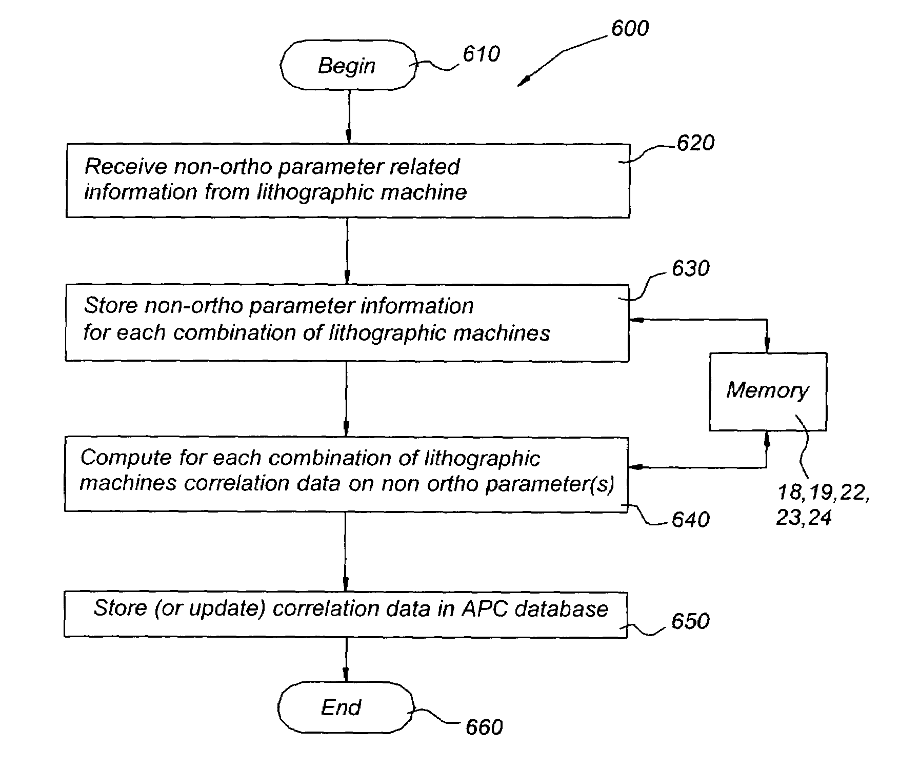
The patent text describes a method for aligning a substrate in a lithographic apparatus by measuring the location and orientation of alignment marks on the substrate. These marks have been defined by a previous lithographic apparatus and the method uses a first substrate grid model with a set of parameters to determine the substrate grid. An additional ortho-scaling parameter is then used to further correct any machine-to-machine differences between the lithographic apparatus and another lithographic apparatus. This method allows for automated process control and reduces the need for off-line time. The computer system includes a processing unit and memory for carrying out this method.

Problems solved by technology

Thus, a large machine-related overlay error may occur since an exposure field in the second lithographic apparatus may be shifted (and / or rotated) relative to the position of the field as used in the first lithographic apparatus.
Such an off-line analysis is troublesome since some time is needed for the off-line measurements.
Thus, a batch can only be processed further after the overlay error has been determined (off-line).
Moreover, the accuracy of the overlay error is not high and only improves when the number of substrates being tested is increased.
Simultaneously, the time needed for off-line inspection increases even further.

Method used


Image

  • Method and system for automated process correction using model parameters, and lithographic apparatus using such method and system
  • Method and system for automated process correction using model parameters, and lithographic apparatus using such method and system
  • Method and system for automated process correction using model parameters, and lithographic apparatus using such method and system

Examples


Embodiment Construction

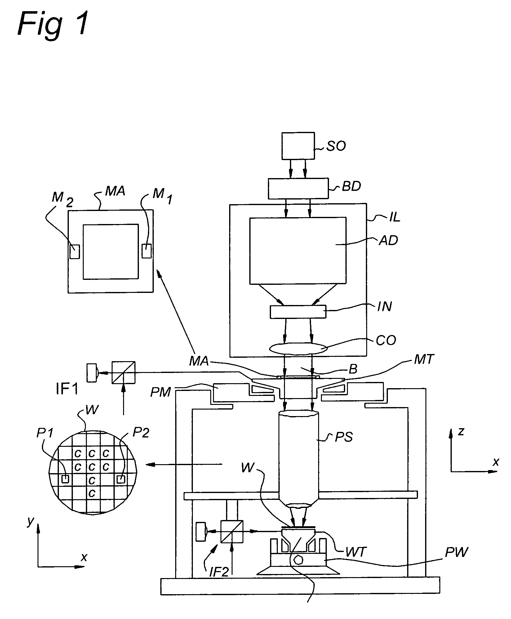
[0032]FIG. 1 schematically depicts a lithographic apparatus according to one embodiment of the invention. The apparatus includes an illumination system (illuminator) IL configured to condition a radiation beam B (e.g. UV radiation), and a support structure (e.g. a mask table) MT constructed to support a patterning device (e.g. a mask) MA and connected to a first positioner PM configured to accurately position the patterning device in accordance with certain parameters. The apparatus also includes a substrate table WT constructed to hold a substrate (e.g. a resist coated substrate) W and connected to a second positioner PW configured to accurately position the substrate in accordance with certain parameters; and a projection system (e.g. a refractive projection lens system) PS configured to project a pattern imparted to the radiation beam B by patterning device MA onto a target portion C (e.g. including one or more dies) of the substrate W.

[0033]The illumination system may include va...


PUM


Abstract

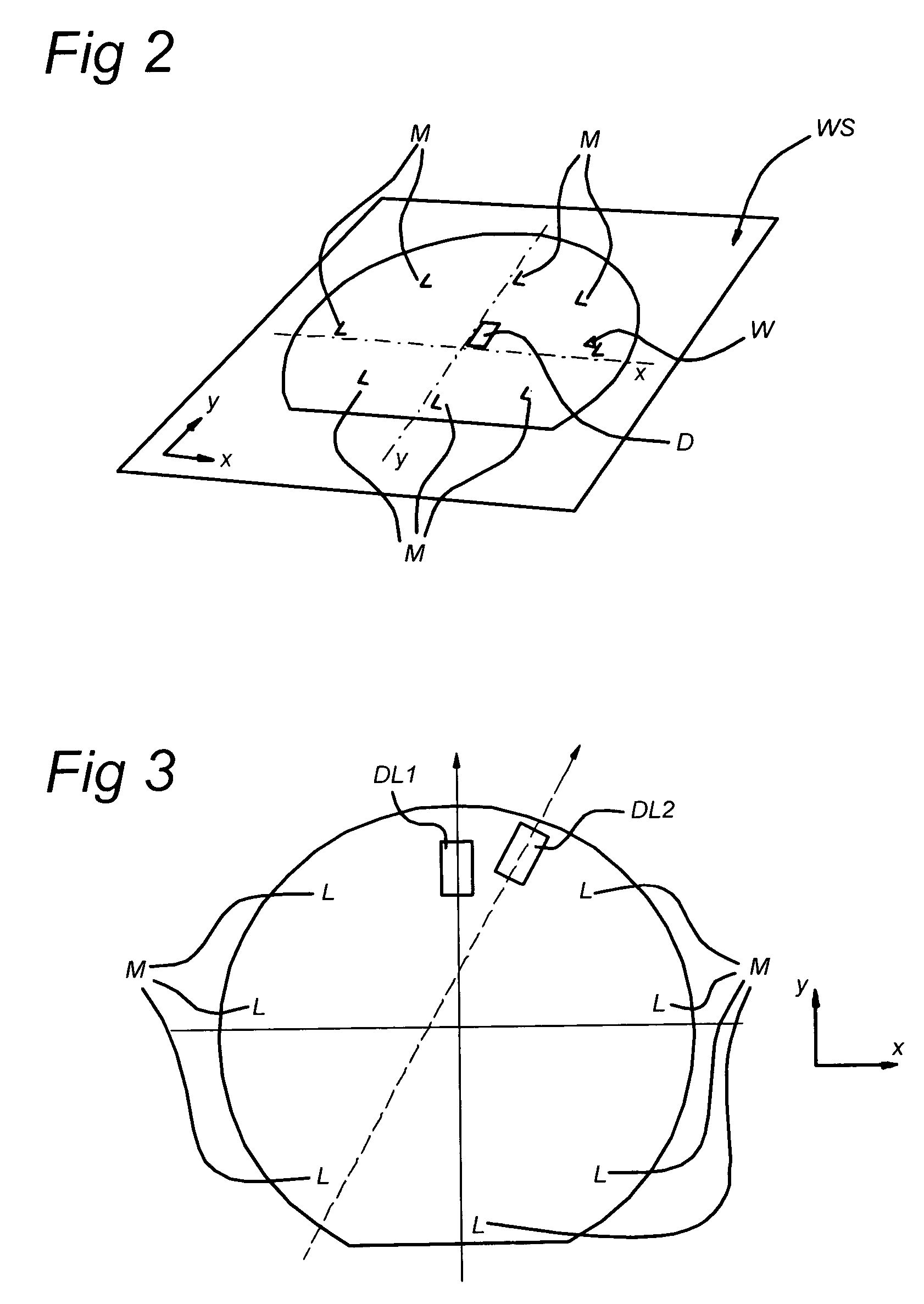
A method for aligning a substrate in a lithographic apparatus is presented. The substrate includes a plurality of alignment marks. The alignment marks have been defined by a second lithographic apparatus and are arranged to provide a substrate grid as a coordinate system that includes a first and a second direction, substantially perpendicular to the first direction. The method includes measuring a location and an orientation of the alignment marks to obtain alignment mark data; determining the substrate grid of the substrate from the alignment mark data by using a first substrate grid model with a first set of parameters; determining the substrate grid of the substrate from the alignment mark data by using a second substrate grid model with a second set of parameters, the second set of parameters including an ortho-scaling parameter in addition to the first set of parameters, and correcting machine-to-machine differences between the lithographic apparatus and the second lithographic apparatus with automated process control data based on the ortho-scaling parameter.

Description

FIELD[0001]The present invention relates to a method for alignment of a substrate on a substrate table. Also, the present invention relates to an automated process control method. Further, the present invention relates to a lithographic apparatus carrying out the method for alignment. Moreover, the present invention relates to a computer system in a lithographic apparatus. Furthermore, the present invention relates to a computer program in accordance with the method for alignment. Also, the present invention relates to a device manufacturing method arranged for use of the method for alignment. Moreover, the present invention relates to an automated process control system arranged for use of the method for alignment.BACKGROUND[0002]A lithographic apparatus is a machine that applies a desired pattern onto a substrate, usually onto a target portion of the substrate.[0003]A lithographic apparatus can be used, for example, in the manufacture of integrated circuits (ICs). In that circumst...

Claims


Application Information

Patent Timeline
Patent Type & Authority Patents(United States)
IPC IPC(8): G03B27/52G03B27/32G03B27/42
CPCG03F9/7003
Inventor EDART, REMI DANIEL MARIE
Owner ASML NETHERLANDS BV
Learn More