Vented high pressure shaft seal

Inactive Publication Date: 2006-10-24
EATON CORP
View PDF16 Cites 4 Cited by
  • Summary
  • Abstract
  • Description
  • Claims
  • Application Information

AI Technical Summary

Benefits of technology

[0008]Accordingly, it is an object of the present invention to provide an improved motor which may operate at increased case pressures without causing faster wear of the shaft seal assembly, thus necessitating more frequent replacement of the shaft seal assembly.
[0009]It is a more specific object of the present invention to provide an improved low-speed, high-torque gerotor motor, having an improved shaft seal assembly, whereby the volumetric efficiency of the motor may be increased, especially at relatively higher inlet pressures, while at the same time achieving increased life of the shaft seal assembly.
[0010]It is an even more specific object of the present invention to provide an improved gerotor motor of the spool valve type in which the volumetric efficiency of the motor may be increased substantially by operating with increased case pressure, without also increasing the rate of wear of the shaft seal, and the frequency of replacement thereof.

Problems solved by technology

It should be noted that the use of spool valve gerotor motors has typically been limited to relatively smaller motors, having relatively lower flow and pressure ratings.
This has been true partly because of certain inherent limitations in spool valve motors, resulting from the radial clearance between the spool valve and the adjacent cylindrical surface (“stationary valve surface”) of the housing.
One of the problems associated with spool valve type gerotor motors is that, as customers seek to continually increase the torque output of the motor by increasing inlet pressure, there is a tendency for the spool valve to “collapse” under the higher pressure, thus increasing the radial clearance between the spool valve surface and the stationary valve surface of the housing.
As noted previously, the increasing radial clearance results in decreasing volumetric efficiency of the motor, which is always undesirable from the viewpoint of the customer.
The typical way of increasing case drain pressure is simply to restrict flow out of the case drain port, thereby causing a buildup in pressure within the case drain region.
Unfortunately, increasing case drain pressure has not been considered an acceptable solution to the collapsing spool problem because the shaft seal assembly (i.e., the seal between the housing and the rotating output shaft) becomes worn much faster than would otherwise be the case, thus necessitating much more frequent downtime of the motor for replacement of the shaft seal assembly.
More frequent replacement of motor shaft seals, and the associated downtime for the motor, is also not acceptable from the viewpoint of the customer.

Method used


Image

  • Vented high pressure shaft seal
  • Vented high pressure shaft seal
  • Vented high pressure shaft seal

Examples


Embodiment Construction

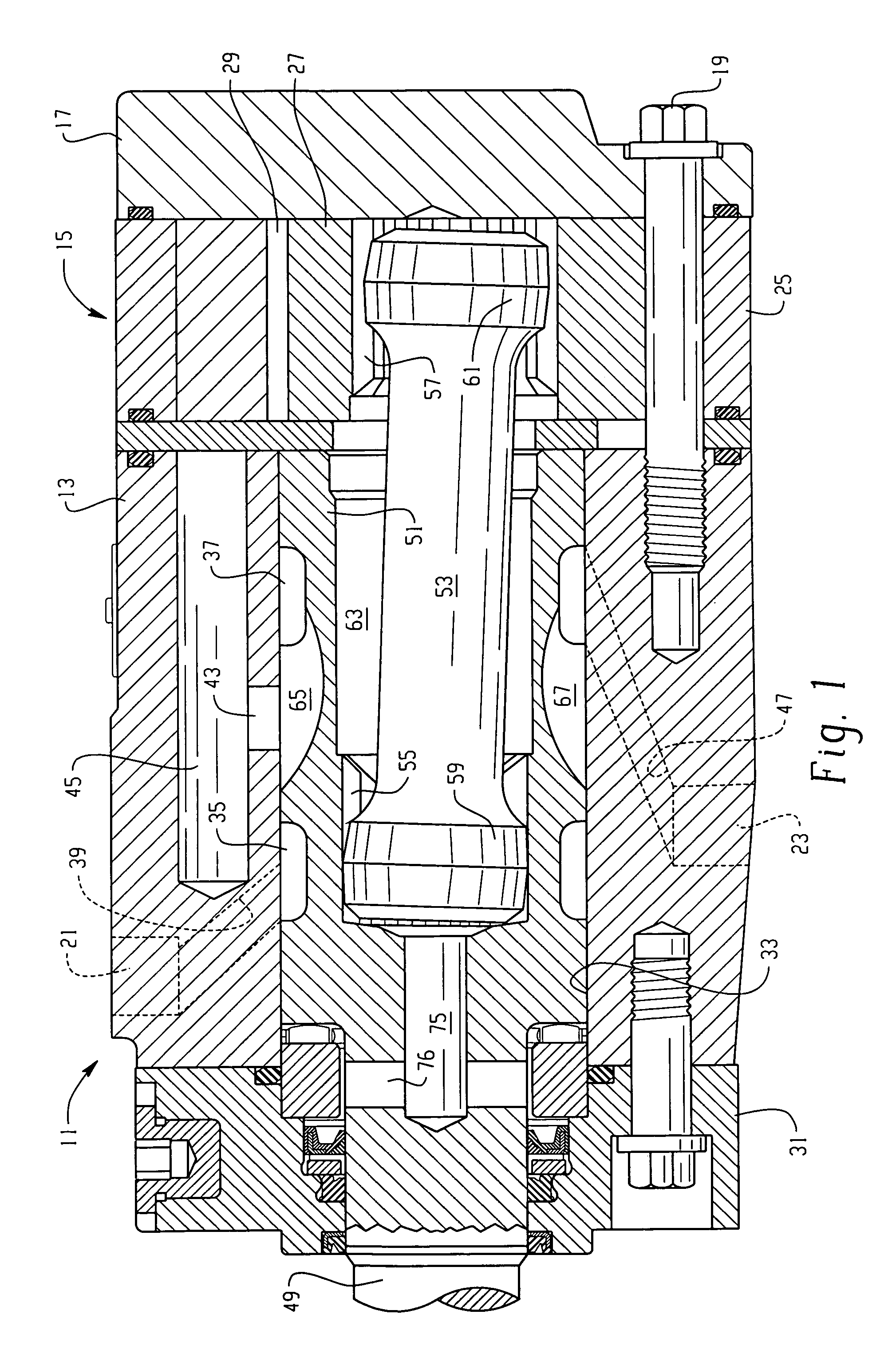
[0017]Referring now to the drawings, which are not intended to limit the invention, FIG. 1 illustrates an axial cross-section of a rotary fluid pressure device of the type to which the present invention may be applied. More specifically, FIG. 1 illustrates a low-speed, high-torque gerotor motor of the spool valve type, generally designated 11, which comprises several distinct sections. The motor 11 comprises a valve housing 13, a fluid energy-translating displacement mechanism, generally designated 15, which, in the subject embodiment, is a roller gerotor gear set. Disposed adjacent the gear set 15 is an end cap 17, and the housing section 13, the gear set 15, and the end cap 17 are held together in fluid sealing engagement by a plurality of bolts 19, only one of which is shown in FIG. 1. The valve housing section 13 includes a fluid inlet port 21 and a fluid outlet port 23. the gerotor gear set 15 includes an internally-toothed ring member 25, having internal teeth typically compri...


PUM


Abstract

A rotary fluid pressure device (11) having a housing (13,31), inlet and outlet ports (21,23), a gerotor gear set (15), a valve member (51) and an input-output shaft (49). A seal assembly (73) is disposed radially between the shaft (49) and the housing (31). The seal assembly comprises, in the order of leakage flow from a case drain region (63), a high pressure shaft seal (77), an annular chamber (71) in which is disposed a rigid back-up member (79;91) for the seal (77), a drain passage (81) communicating from the annular chamber (71) to a case drain port (47), and a low pressure shaft seal (83). The back-up member (79;91) may cooperate with either the housing (31) or the seal (77) or the input-output shaft (49) to define a fluid passage (87,89;93,95), so that any leakage flow past the high pressure shaft seal (77) flows through the drain.

Description

CROSS-REFERENCE TO RELATED APPLICATIONS[0001]This application is a continuation-in-part (CIP) of application U.S. Ser. No. 10 / 167,218, filed Jun. 11, 2003 now abandoned, in the name of James M. LeClair, Jr., Jarett D. Millar and Andrew T. Miller for a “VENTED HIGH PRESSURE SHAFT SEAL”.BACKGROUND OF THE DISCLOSURE[0002]The present invention relates to rotary fluid pressure devices, such as low-speed, high-torque (LSHT) gerotor motors, and more particularly, to an improved high pressure shaft seal assembly for use in such devices.[0003]Gerotor motors of the LSHT type are normally classified, in regard to their valving configuration, as being of either the “spool valve” or “disc valve” type. As used herein, the term “spool valve” refers to a generally cylindrical valve member in which the valving action occurs between the cylindrical outer surface of the spool valve and the adjacent internal cylindrical surface (bore) of the surrounding housing. By way of contrast, the term “disc valve...

Claims


Application Information

Patent Timeline
IPC IPC(8): F04C15/00F16J15/32F03C2/08F01C1/10F01C19/12F01C21/00F04C2/10
CPCF01C1/105F01C19/125F01C21/005F04C2/106
Inventor LECLAIR, JR., JAMES M.MILLAR, JARETT D.MILLER, ANDREW T.
Owner EATON CORP
Why Eureka
Try Eureka