
Method of manufacturing insulated coil

a manufacturing method and coil technology, applied in the direction of transformer/inductance core, magnet, magnetic body, etc., can solve the problems of uneven difficulty in wounding the insulation tape around the coil conductor, and the thickness of the insulating layer itself becoming thicker, so as to achieve excellent voltage endurance characteristics and high thermal conduction , the effect of not increasing the thickness of the insulating layer

Active Publication Date: 2006-10-17
MITSUBISHI ELECTRIC CORP
View PDF8 Cites 46 Cited by
  • Summary
  • Abstract
  • Description
  • Claims
  • Application Information

AI Technical Summary

Benefits of technology

The present invention provides a method for manufacturing an insulation coil with excellent voltage endurance characteristics and high thermal conduction. The method involves forming a layer of inorganic particles between mica flake layers without increasing the thickness of the insulating layer. The resulting insulation coil has a thermally conductive layer with inorganic particles having high thermal conductivity on the surface, which improves its performance in voltage endurance and thermal conduction.

Problems solved by technology

Accordingly, according to the method of manufacturing an insulation coil, there are problems in that the insulation tape is wound around the coil conductor with difficulty, and a thickness of the insulating layer becomes uneven and thicker.
Furthermore, according to the second through fourth methods of manufacturing an insulation coil, there are problems in that the inorganic particle layer is formed thicker on the insulation tape, the inorganic particle layer between the mica flake layers becomes thicker, resulting in the insulating layer itself becoming thicker.
However, since the insulation coil is inserted in a slot groove of a stator of an electric rotating machine, a thickness of the insulating layer of the insulation coil is restricted.
Accordingly, according to existing methods of manufacturing an insulation coil, there are problems in that the insulation tape becomes thicker, the number of layers of mica layer in the insulating layer becomes smaller, and deterioration of the voltage endurance characteristics results.

Method used

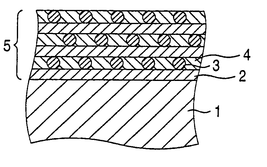
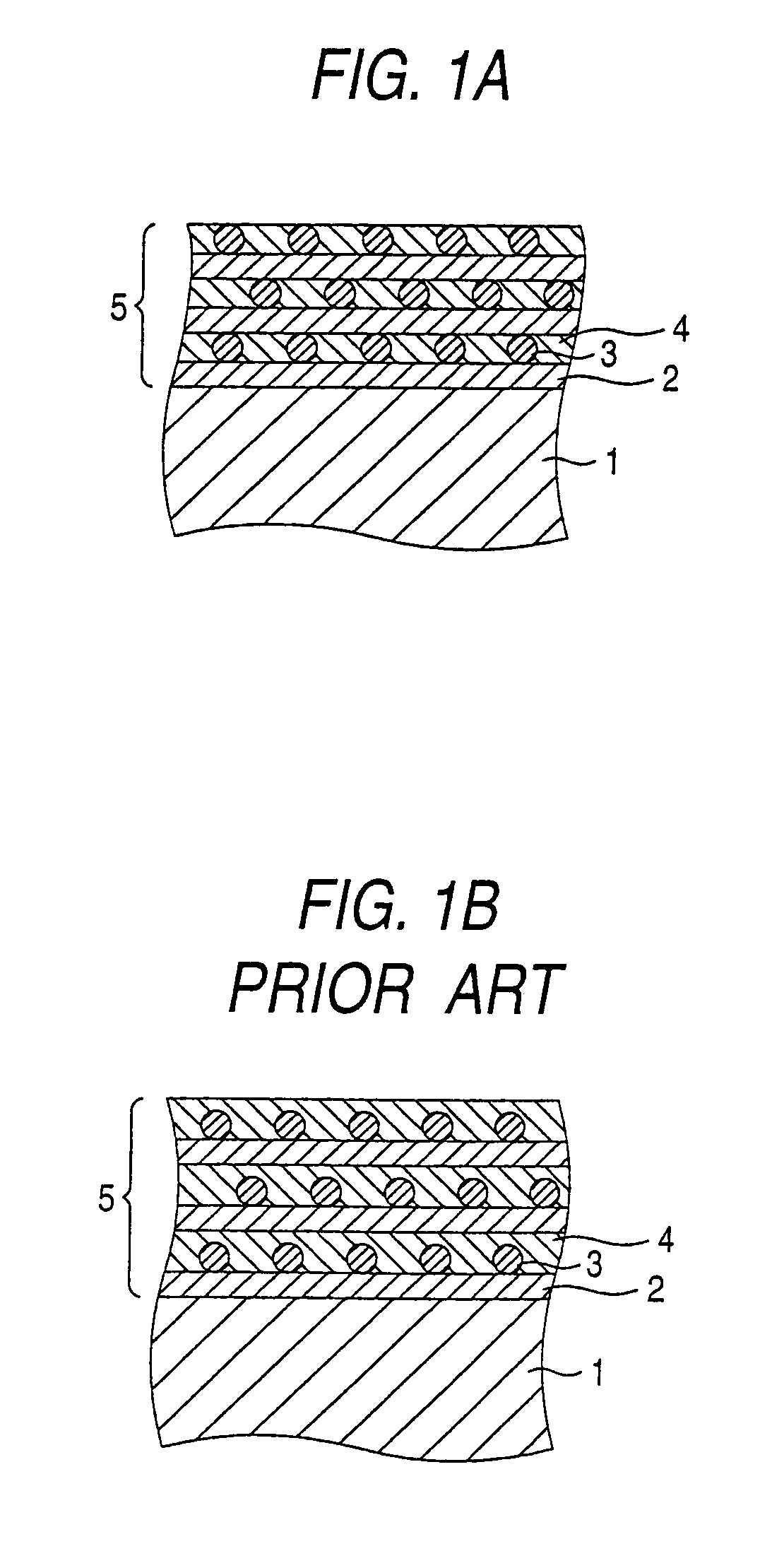

Image

  • Method of manufacturing insulated coil
  • Method of manufacturing insulated coil
  • Method of manufacturing insulated coil

Examples


embodiment 1

[0021]A method of manufacturing an insulation coil in an embodiment 1 according to the invention includes the respective steps below.

[0022]On a mica sheet obtained by paper making reconstituted mica dispersed in water with a paper machine, a resin dissolved in a solvent is coated by means of a roll coater method or a spray method followed by volatilizing the solvent, and thereby a resin-stuck mica layer sheet is obtained.

[0023]Furthermore, on glass cloth that is a reinforcement of the mica layer sheet, a resin dissolved in a solvent is coated by means of a roll coater method or a spray method followed by volatilizing the solvent, and thereby resin-stuck glass cloth is obtained.

[0024]In the next place, the resin-stuck mica layer sheet and the resin-stuck glass cloth are stacked, heated under pressure by undergoing a heat roller at a temperature of 60 to 70 degree centigrade to stick the glass cloth that is a reinforcement to the mica layer sheet, and thereby a mica layer sheet reinfo...

example 1

[0047]Reconstituted mica powder is dispersed in water, the dispersion solution is subjected to paper making by use of a paper machine and thereby a reconstituted mica foil is prepared. On the reconstituted mica foil, a resin composition in which 100 parts by weight of bisphenol A epoxy resin (product name: Epikote 834, manufactured by Japan Epoxy Resin Co., Ltd.) and 10 parts by weight of zinc naphthenate are dissolved in 400 parts by weight of methyl ethyl ketone is coated by use of a roll coater method and at the same time the reconstituted mica foil is laminated on a polyester film having a width of 1000 mm, a thickness of 0.02 mm and a predetermined length that is a tentative support, and thereby a mica layer sheet having a finished thickness of the mica layer of 0.1 mm is prepared.

[0048]A resin composition that is prepared by blending 100 parts by weight of bisphenol A epoxy resin (product name: Epikote 834, manufactured by Japan Epoxy Resin Co., Ltd.), 10 parts by weight of zi...

example 2

[0057]With the exception that the layer of mixture was cut with the gap of the doctor blade set at 0.1 mm, similarly to example 1, a model insulation coil was prepared. The thermal conductivity and the voltage endurance characteristics of the insulating layer of the obtained model insulation coil were obtained similarly to example 1 and measurements are shown in Table 1.


PUM

PropertyMeasurementUnit
thicknessaaaaaaaaaa
particle diameteraaaaaaaaaa
widthaaaaaaaaaa

Abstract

On a surface of a glass cloth adhered a mica layer sheet, a mixture of inorganic particles having a thermal conductivity of at least 5 W / mK, a resin, and a solvent is applied to form a layer of the mixture of the inorganic particles, the resin, and the solvent; the layer of the mixture is reduced in thickness using a doctor blade, followed by pressurizing to form a high thermally conducting layer; the mica layer sheet on which the high thermally conducting layer is disposed is cut to obtain a mica insulating tape; and the mica insulation tape is wound around a coil conductor. As a result, an insulated coil that is excellent in the voltage endurance characteristics and has a high thermal conductivity is manufactured.

Description

BACKGROUND OF THE INVENTION[0001]1. Field of the Invention[0002]The present invention relates to a method of manufacturing an insulation coil for use in an electric rotating machine, in particular, a method of manufacturing an insulation coil excellent in the insulating properties and the thermal conduction.[0003]2. Description of the Related Art[0004]In a high output electric rotating machine, it is necessary, in order to efficiently dissipate generated heat, to improve the thermal conductivity of an insulation coil. So far, it has been tried to use high thermal conduction insulating material in an electrically insulating coating of an insulation coil.[0005]As a coil insulated with a high thermal conduction insulating material, there is a coil insulated with an insulating material that includes mica flake layers solidly fixed to glass fabric; and a resin layer that is disposed in a space between the mica flake layers and contains inorganic particles such as boron nitride, aluminum ...

Claims


Application Information

Patent Timeline
Patent Type & Authority Patents(United States)
IPC IPC(8): H01F7/06H01F5/06H01F27/32H01F41/06H01F41/12H02K3/30H02K3/34H02K3/40H02K9/00H02K15/10H02K15/12
CPCH01F5/06H01F41/122H02K3/30H02K3/40H02K15/105Y10T29/49002H01F41/062H02K9/00Y10T29/49128Y10T29/49798Y10T29/49071Y10T29/49073Y10T29/49124Y10T29/4902H01F27/323H01F41/068
Inventor YAMAMOTO, SHIGEYUKIBITO, WATARUISOOKA, TOSHIOGOSHIMA, KOICHI
Owner MITSUBISHI ELECTRIC CORP
Learn More