
Image data compressing apparatus

Inactive Publication Date: 2006-10-10
FUJIFILM CORP +1
View PDF5 Cites 2 Cited by
  • Summary
  • Abstract
  • Description
  • Claims
  • Application Information

AI Technical Summary

Benefits of technology

[0006]Accordingly, an object of the present invention is to render the amount of image data after compression substantially constant.
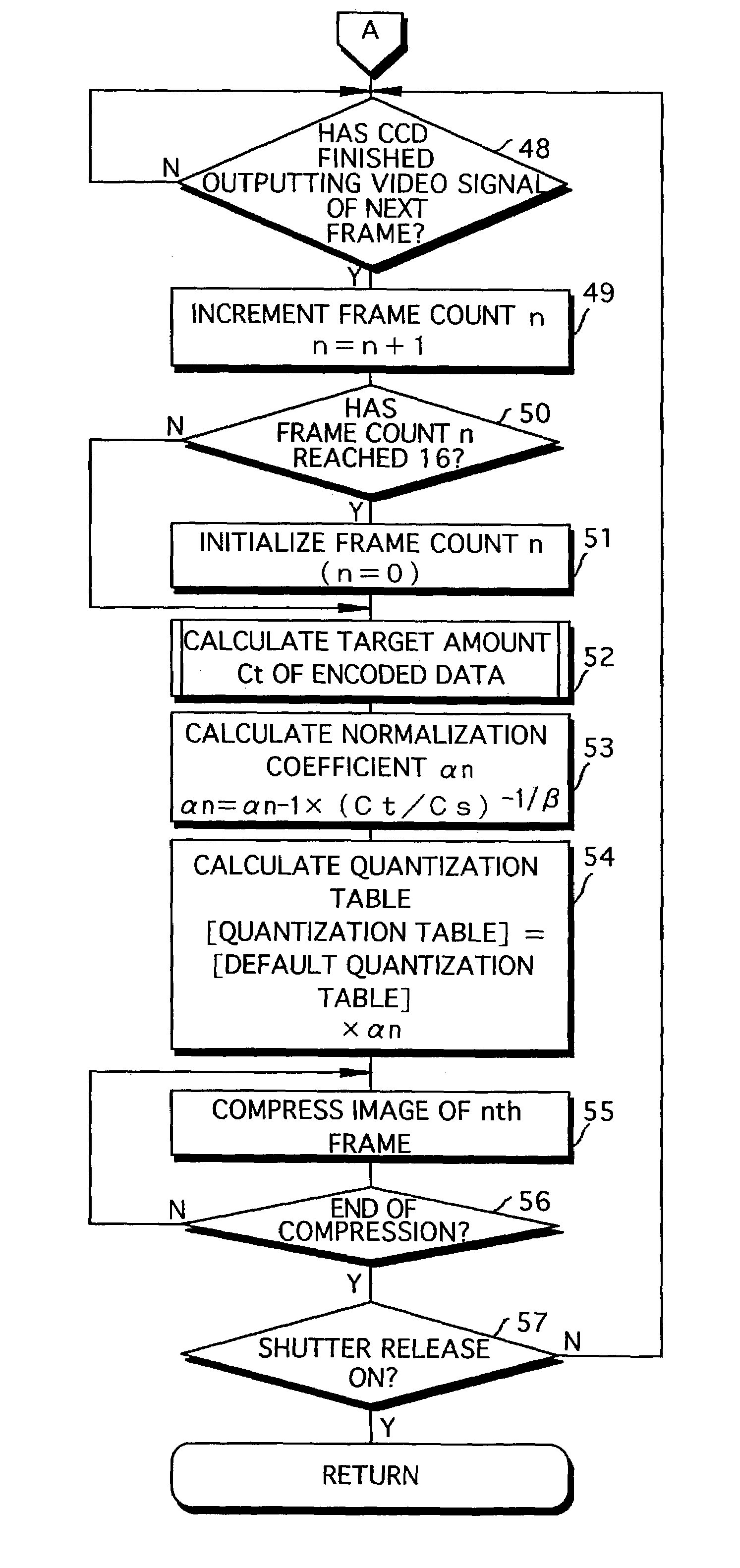
[0009]The present invention is such that when encoded data is stored in the storage area, the encoded data device is controlled in such a manner that the encoded will become an amount of data obtained by averaging residual storage capacity of a remaining area of the storage area using a number of image frames represented by encoded data to be stored in the remaining area. Since the encoded data is generated in accordance with the residual capacity of the remaining area in such a manner that the amount of data is averaged, it is possible to prevent a drastic change in the amount of encoded data even if there is a change of scene. Accordingly, a drastic change in image quality from frame to frame can be prevented. In addition, the amount of encoded data per unit time can be rendered substantially constant. Encoded data that has thus been stored in the storage area is applied to and recorded on a storage medium such as a memory card.
[0012]In any case, the amount of encoded data of the last frame becomes substantially constant. As a result, the image quality of the last frame can be prevented from changing drastically.
[0013]In a case where the storage area includes an apparent storage area that stores the plurality of frames of encoded data and a margin storage area that stores a prescribed amount of encoded data, the encoding controller may control the encoded data device, in regard to the last frame of encoded data to be stored in the storage area, in such a manner that the encoded data will become an amount of data that is less than twice the residual capacity of the remaining area of the apparent storage area. Since the amount of encoded data will be large for the last frame, a high image quality can be maintained for this frame.

Problems solved by technology

However, if the compression rate of each individual frame is fixed, the amount of compressed image data may change drastically when the scene changes.
If this occurs, the amount of compressed image data per unit time cannot be rendered substantially constant.

Method used


Image

  • Image data compressing apparatus
  • Image data compressing apparatus
  • Image data compressing apparatus

Examples


Embodiment Construction

[0025]A preferred embodiment of the present invention will now be described with reference to the drawings.

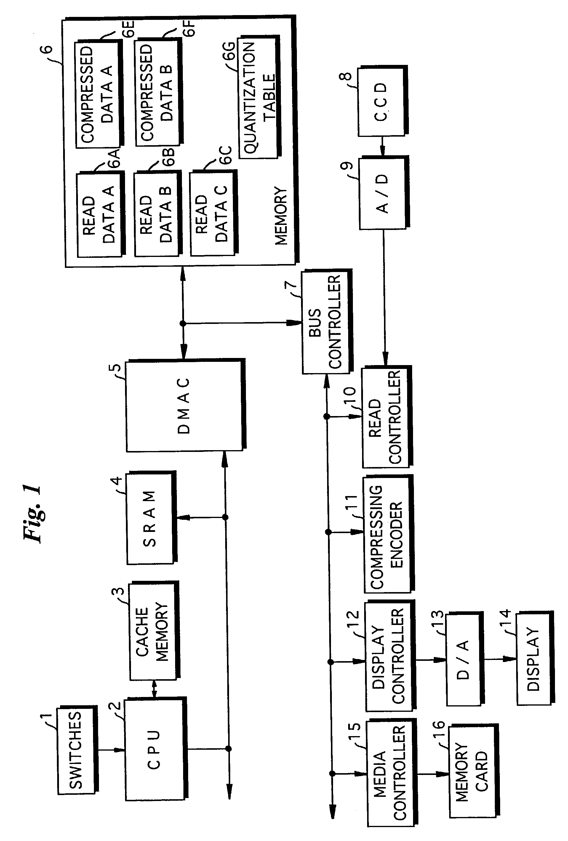
[0026]FIG. 1 is a block diagram illustrating the electrical structure of a digital camera embodying the present invention.

[0027]The overall operation of the digital camera is controlled by a CPU 2.

[0028]The digital camera has switches 1 that include a mode setting switch for setting various modes such as a movie photography mode and a still photography mode, and a shutter-releaser button, etc. Various signals from the switches 1 are input to the CPU 2. A cache memory 3 for storing data temporarily is connected to the CPU 2.

[0029]The digital camera further includes a DMAC (Direct Memory Access Controller) 5. The latter controls the writing of image data, which has been obtained by imaging, to a memory 6 as well as the reading of image data that has been written to the memory 6. The digital camera further includes an SRAM (Static Random-Access Memory) 4.

[0030]The memory 6 include...


PUM


Abstract

When an nth frame of encoded data is stored in a compressed-data storage area that stores 15 frames of encoded data, a target amount of code of the nth frame is decided so as to become a value that is the result of dividing the residual capacity of an area remaining in the compressed-data storage area by the number of remaining images to be stored in this remaining area. This makes it possible to prevent the target amount of code from becoming very large or very small. Even if there is a change in a photographic scene, therefore, a drastic change in image quality from frame to frame can be prevented.

Description

BACKGROUND OF THE INVENTION[0001]1. Field of the Invention[0002]This invention relates to an image data compressing apparatus for generating encoding data by subjecting image data representing one frame of an image to calculation of orthogonal transform coefficients, quantization of the orthogonal transform coefficients and encoding of the quantized orthogonal transform coefficients, and storing the generated encoded data in a storage area having a capacity for storing a plurality of frames of encoded data.[0003]2. Description of the Related Art[0004]The motion JPEG (Joint Photographic Experts Group) format is one example of a moving image compression format. According to motion JPEG, image data obtained by subjecting a plurality of frames of still images to JPEG compression is expanded and displayed continuously to thereby present the image data as a moving image. In order to hold the recording time of the moving image substantially constant in such a moving image compression forma...

Claims


Application Information

Patent Timeline
IPC IPC(8): G06K9/36G06K9/46H04N5/225G06T9/00G11B20/10H03M7/30H04N5/91H04N5/92H04N19/124H04N19/126H04N19/152H04N19/172H04N19/196H04N19/423H04N19/60
CPCH04N19/172H04N19/15H04N19/60H04N19/126
Inventor FUNAMOTO, KENJI
Owner FUJIFILM CORP
Learn More