
Bandgap reference circuit for ultra-low current applications

a reference circuit and ultra-low current technology, applied in the direction of electric variable regulation, process and machine control, instruments, etc., can solve the problem of inpractical integration of resistors of this size, and achieve the effect of facilitating current sinking and reducing the minimum supply voltage requiremen

Active Publication Date: 2006-10-03
TEXAS INSTR INC
View PDF5 Cites 8 Cited by
  • Summary
  • Abstract
  • Description
  • Claims
  • Application Information

AI Technical Summary

Benefits of technology

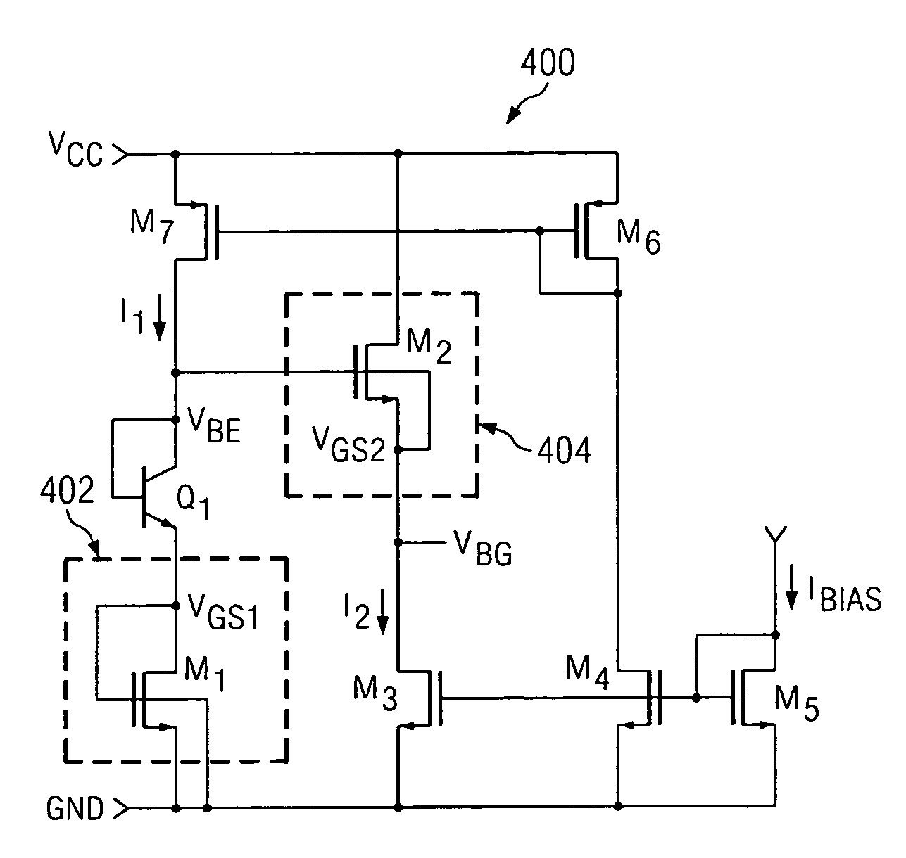
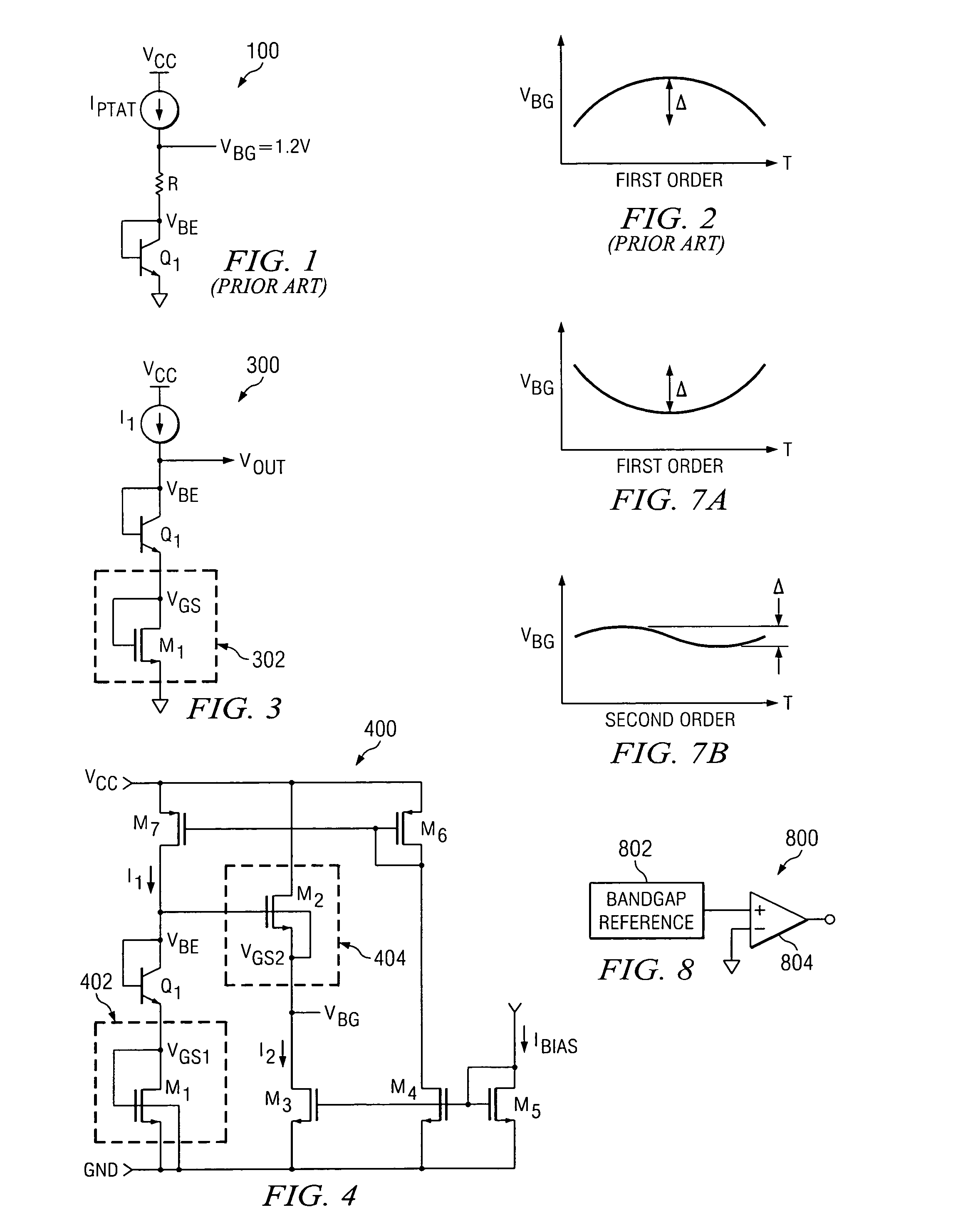
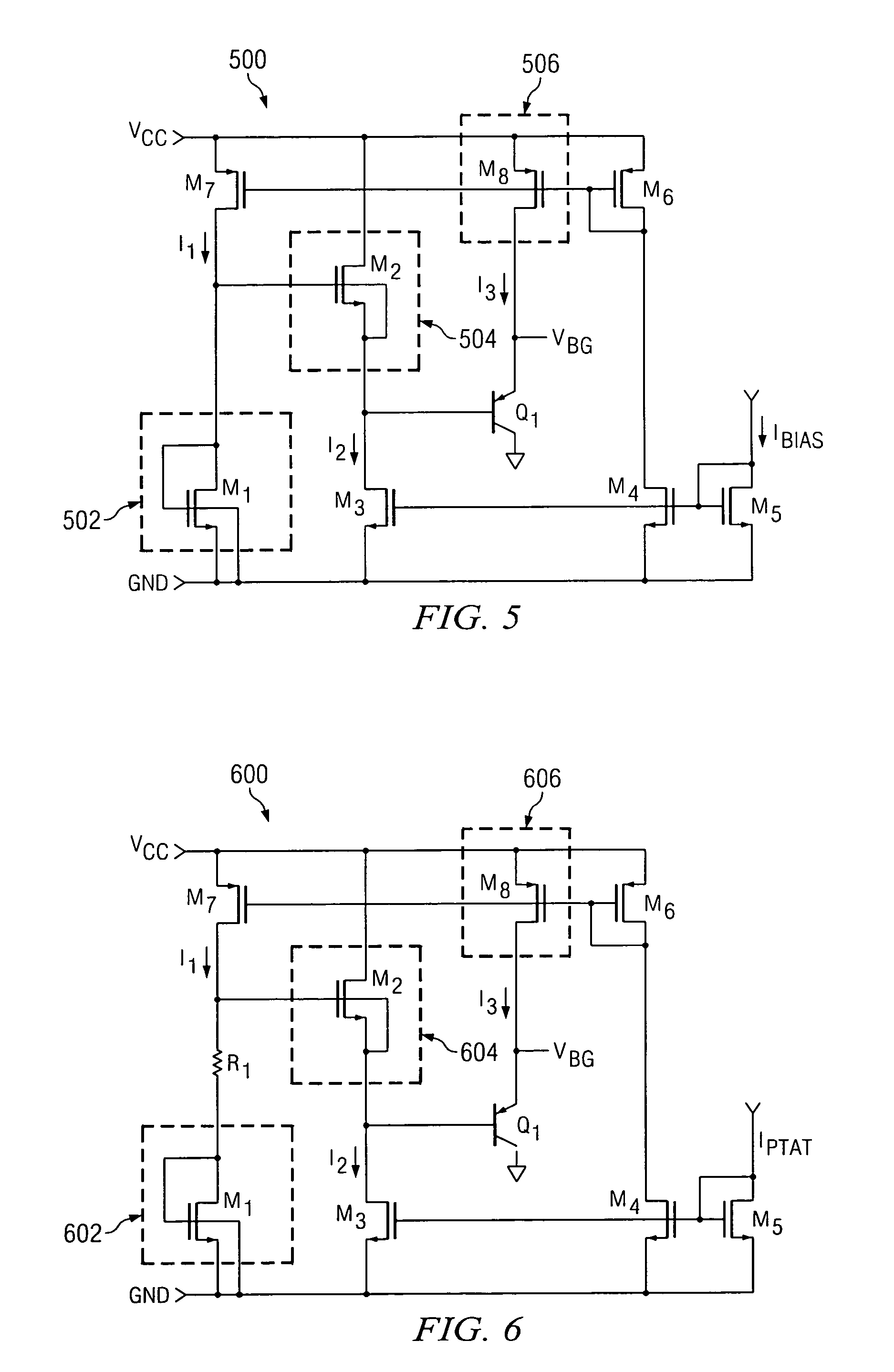
[0008]In accordance with another exemplary embodiment of the present invention, an exemplary bandgap circuit can be configured to reduce a minimum supply voltage requirement. For example, an input supply voltage of less than two volts can be utilized for operation of a bandgap circuit for low-current applications. In accordance with an exemplary embodiment, an exemplary bandgap circuit can comprise a third current source to provide an additional bias current to facilitate the sinking of current.
[0009]In accordance with another exemplary embodiment of the present invention, an exemplary bandgap circuit can also be configured for curvature-correction to address the VBE characteristics of first order bandgap circuits. For example, an exemplary bandgap circuit can comprise a positive temperature coefficient generated by both a FET device and a resistor device. As a result, a more stable temperature-dependent voltage reference over a wider temperature range can be realized.

Problems solved by technology

Integrated resistors of this size are not practical due to space limitations.

Method used


Image

  • Bandgap reference circuit for ultra-low current applications
  • Bandgap reference circuit for ultra-low current applications
  • Bandgap reference circuit for ultra-low current applications

Examples


Embodiment Construction

[0019]The present invention may be described herein in terms of various functional components and various processing steps. It should be appreciated that such functional components may be realized by any number of hardware or structural components configured to perform the specified functions. For example, the present invention may employ various integrated components, e.g., buffers, supply rail references, current mirrors, and the like, comprised of various electrical devices, e.g., resistors, transistors, capacitors, diodes and the like whose values may be suitably configured for various intended purposes. In addition, the present invention may be practiced in any integrated circuit application where stable voltage references are desired. Further, it should be noted that while various components may be suitably coupled or connected to other components within exemplary circuits, such connections and couplings can be realized by direct connection between components, or by connection...


PUM


Abstract

A bandgap reference circuit as may be used in ultra-low current applications is provided. An exemplary bandgap circuit can be configured to generate a positive temperature coefficient without the need for a resistor to offset a negative temperature coefficient. In accordance with an exemplary embodiment of the present invention, a bandgap circuit comprises a negative temperature coefficient generated from a junction device and a positive temperature coefficient generated from an FET-based device. An exemplary junction device can comprise a bipolar, junction diode or any other device for generating a negative temperature coefficient, while an exemplary FET-based device comprises a gate-drain connected device configured to provide a gate-source voltage having a positive temperature coefficient coupled in series with the bipolar device. In accordance with another exemplary embodiment, the bandgap circuit can be configured with a threshold voltage elimination device comprising a second FET-based device configured to subtract out a threshold voltage component of the first FET-based device.

Description

FIELD OF INVENTION[0001]The present invention relates to a bandgap reference for use in integrated circuits. More particularly, the present invention relates to a bandgap reference circuit as may be used in ultra-low current applications.BACKGROUND OF THE INVENTION[0002]The demand for less expensive, and yet more reliable integrated circuit components for use in mobile communication, imaging and high-quality video applications continues to increase rapidly. As a result, integrated circuit manufacturers are requiring greater accuracy in voltage references for such components and devices to meet the design requirements of such myriad emerging applications.[0003]Voltage references are generally required to provide a substantially constant output voltage despite gradual or momentary changes in input voltage, output current or temperature. In particular, many designers have utilized bandgap reference circuits due to their ability to provide a stable voltage supply that is insensitive to ...

Claims


Application Information

Patent Timeline
Patent Type & Authority Patents(United States)
IPC IPC(8): G05F3/26G05F3/20
CPCG05F3/30
Inventor TEEL, JOHN C.LARSON, TONY R.
Owner TEXAS INSTR INC
Learn More