
Valve-free oxygen concentrator featuring reversible compressors

a compressor and valve-free technology, applied in the direction of positive displacement liquid engine, piston pump, separation process, etc., can solve the problems of rubbing and prone to excessive heat, and achieve the effect of improving oxygen concentration and enhancing nitrogen purification

Inactive Publication Date: 2006-10-03
BASSINE STUART
View PDF11 Cites 38 Cited by
  • Summary
  • Abstract
  • Description
  • Claims
  • Application Information

AI Technical Summary

Benefits of technology

[0005]It is a further object of this invention to provide reversible pivoting vane rotary compressors which generate a consistent, balanced and interrupted air flow to the nitrogen filters of an oxygen concentrator so that a consistent high level of concentrated oxygen is produced over a given time.
[0016]A protective shield may be mounted on each side of the rotor. The shield extends diametrically beyond the circumferential surface of the rotor and protects the side of the pivoting vanes from rubbing against the side walls.

Problems solved by technology

In prior pivoting vane compressors, the vane tend to exhibit premature wear as a result of rubbing against the side walls of the compression chamber.
Such rubbing also tends to generate excessive heat.

Method used


Image

  • Valve-free oxygen concentrator featuring reversible compressors
  • Valve-free oxygen concentrator featuring reversible compressors
  • Valve-free oxygen concentrator featuring reversible compressors

Examples


Embodiment Construction

[0018]Other objects, features and advantages will occur from the following description of a preferred embodiment and the accompanying drawings, in which:

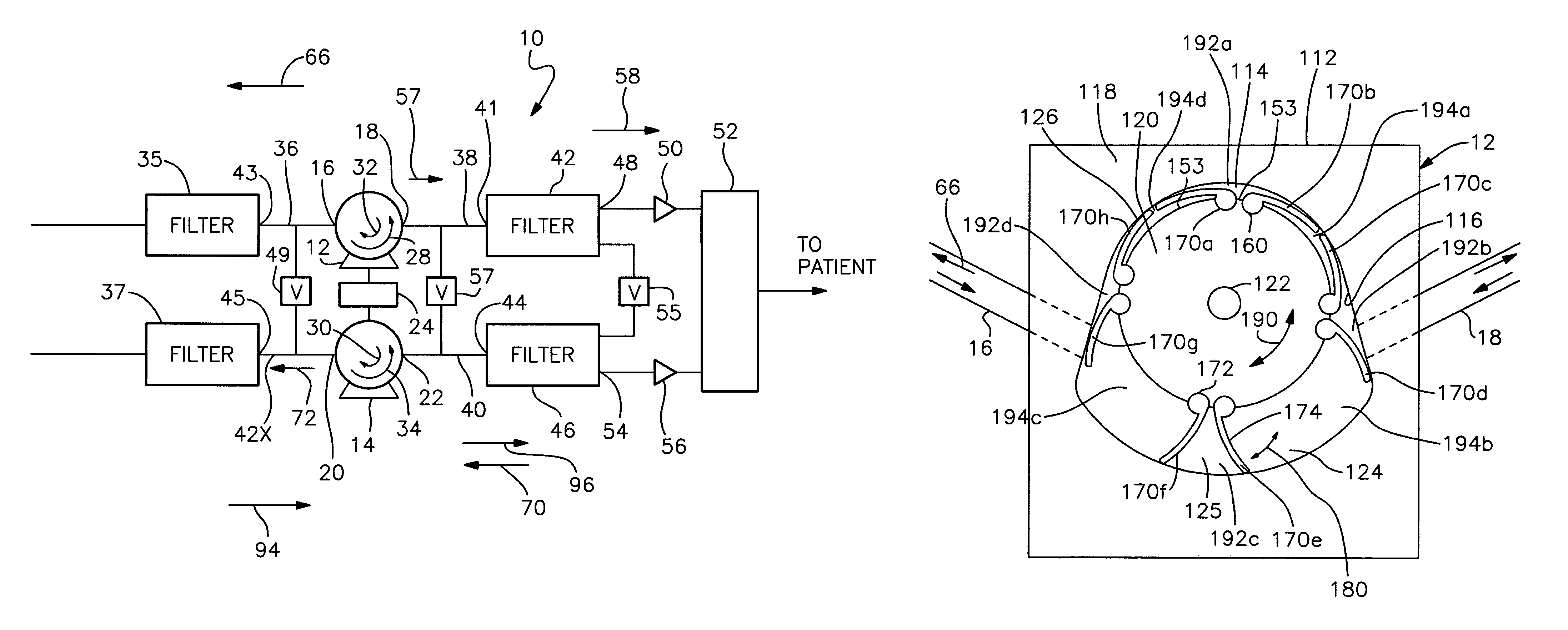
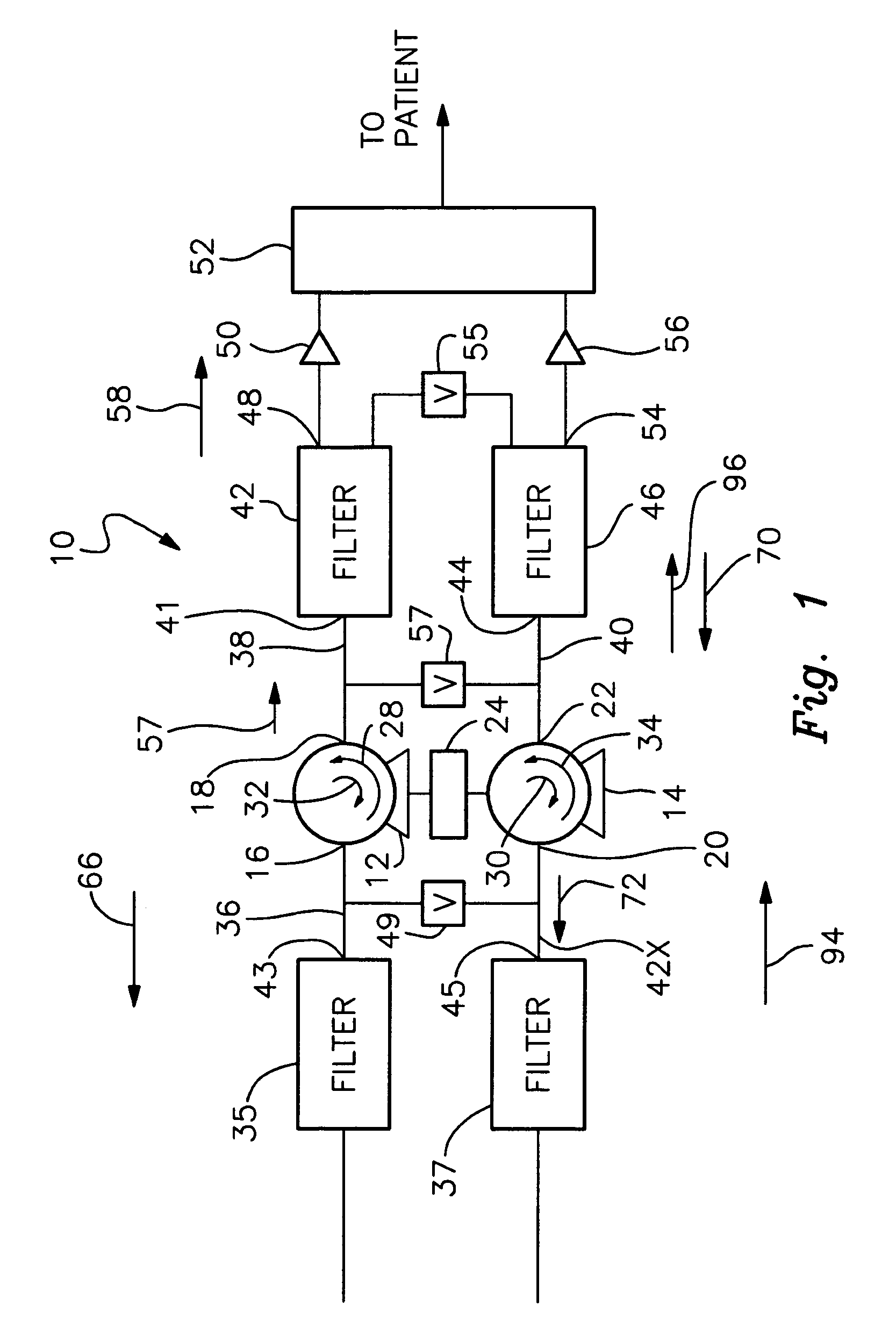
[0019]FIG. 1 is a schematic view of a preferred valve-free oxygen concentrator according to this invention, which includes a pair of rotary compressors constructed in accordance with this invention;

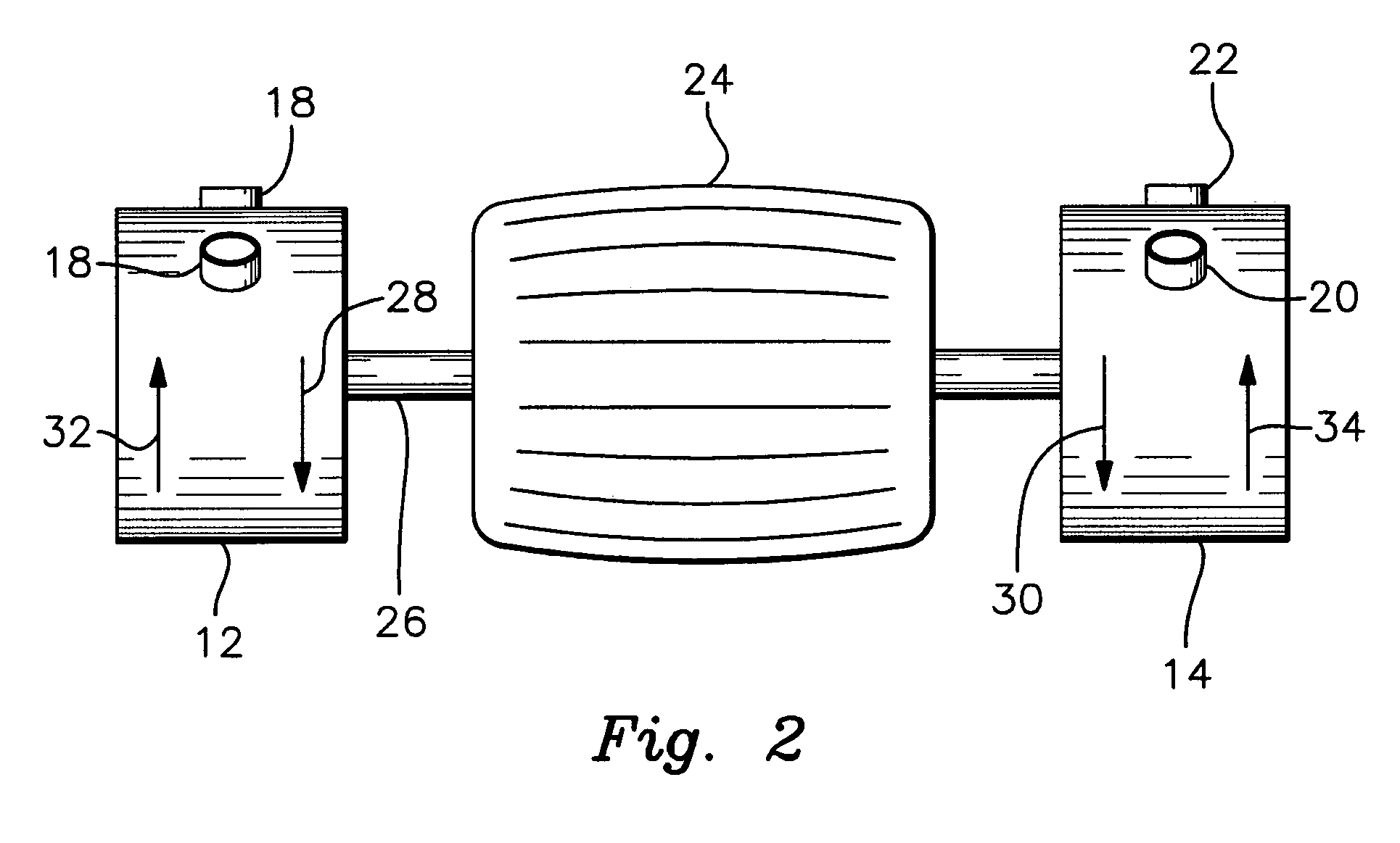
[0020]FIG. 2 is an elevational view of the reversible motor and interconnected rotary compressors used in the concentrator;

[0021]FIG. 3 is an elevational, partly cut away view of a preferred embodiment of the compressor of this invention;

[0022]FIG. 4 is a schematic view of the reversible dual compressor assembly with reversible fans mounted within a cabinet;

[0023]FIG. 5 is a schematic view of an alternative compressor housing;

[0024]FIG. 6A is an elevational side view of a compressor assembly utilized in this invention;

[0025]FIG. 6B is a simplified side view of a compressor with the side wall removed and the pear-shaped compression chamber...


PUM


Abstract

A pivoting vane rotary compressor includes a housing having a generally pear-shaped chamber. A rotor mounted within the chamber defines a main and constricted chamber regions. Reversible intake and exhaust ports alternately introduce air into and exhaust air from the chamber. The rotor carries pivotable vanes and a motor drives the rotor alternately in opposing first and second directions to open the vanes and define compartments that transmit the air through the chamber between the ports. Air introduced through one of the ports is compressed and discharged through the other port. A concentrator employs a pair of these compressors as well as associated filters and crossover valves.

Description

FIELD OF THE INVENTION[0001]This invention relates to a pivoting vane rotary compressor having a generally pear-shaped compression chamber. The invention further relates to a valve-free oxygen concentrator using the compressor.BACKGROUND OF THE INVENTION[0002]Conventional oxygen concentrators often employ a rotary compressor to pump air through the concentrator and to the patient. Traditionally, the compressor employed sliding carbon vanes. Such compressors do not exhibit optimal air displacement and oxygen production for the reasons discussed in my issued U.S. Pat. Nos. 5,188,524, 5,968,236, 6,371,745 B1 and pending application Ser. No. 10 / 132,627 filed Apr. 16, 2002. As described in the foregoing references, I have provided a reversible pivoting vane rotary compressor and a valve-free oxygen concentrator, which provide for significantly improved air displacement and concentrated oxygen production. Nonetheless, a need continues to exist for even greater air displacement, more effic...

Claims


Application Information

Patent Timeline
IPC IPC(8): F04C18/00F03C2/00
CPCF04C18/44F04C23/003F04C23/008F04C28/04F04C29/0092
Inventor BASSINE, STUART
Owner BASSINE STUART
Learn More